LH79524/LH79525 User’s Guide Watchdog Timer
Version 1.0 19-7
19.2.2.3 Status Register (STATUS)
This register, described in Table 19-6 and Table 19-7, provides the status of the WDT
interrupts, and allows programming whether a system reset is generated upon the first
timeout, or if an interrupt is generated on the first timeout, followed by a system reset if
that interrupt is not serviced before a second timeout occurs.
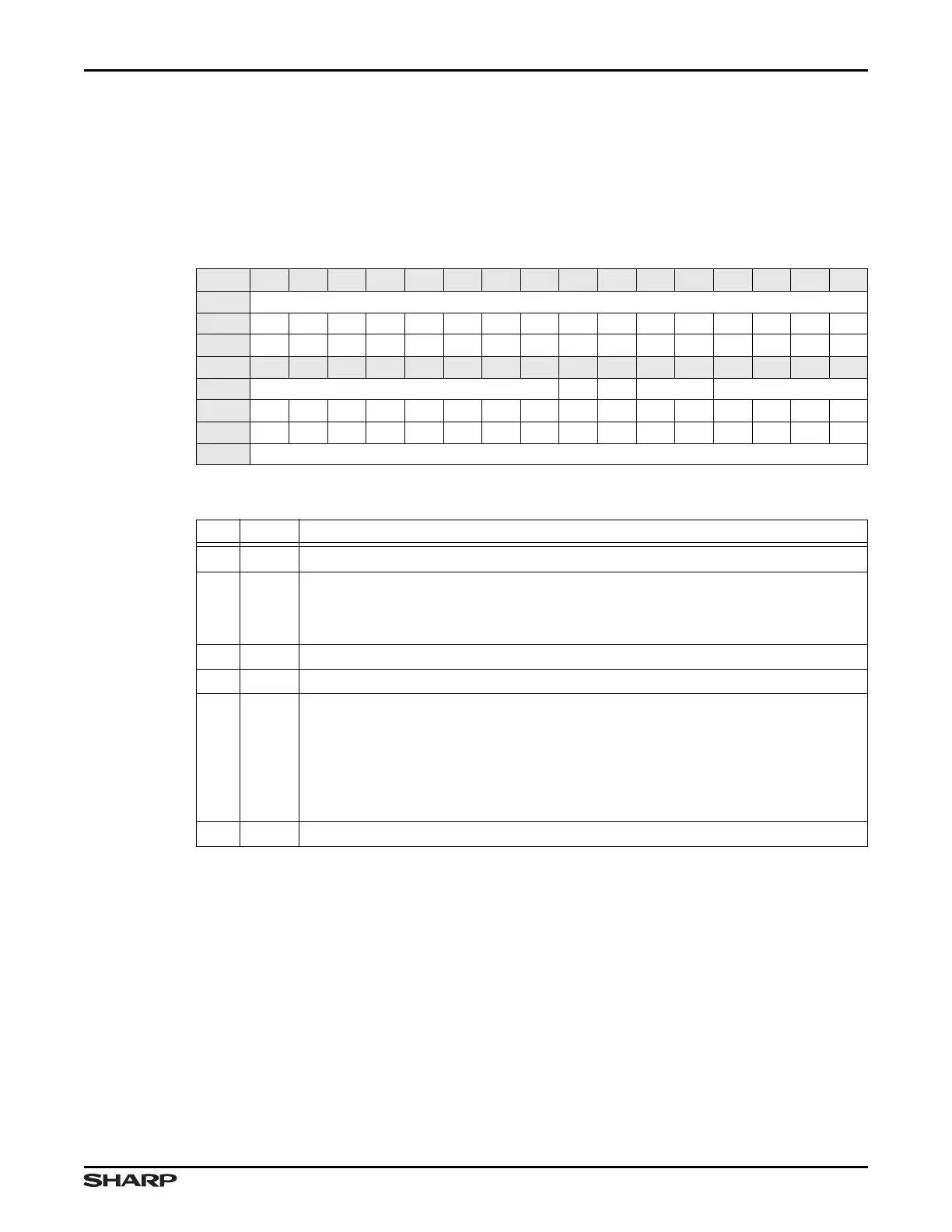
Table 19-6. STATUS Description
BIT 31 30 29 28 27 26 25 24 23 22 21 20 19 18 17 16
FIELD ///
RESET 0000000000000000
TYPE RO RO RO RO RO RO RO RO RO RO RO RO RO RO RO RO
BIT 15 14 13 12 11 10 9 8 7 6 5 4 3 2 1 0
FIELD /// INT /// IF ///
RESET 0000000001 000000
TYPE RO RO RO RO RO RO RO RO RO RO RO RO RO RO RO RO
ADDR 0xFFFE3000 + 0x08
Table 19-7. STATUS Fields
BIT NAME DESCRIPTION
31:8 /// Reserved Reading this field returns 0. Write the reset value.
7INT
INT This bit reports the WDT timeout interrupt status:
1 = An interrupt has occurred and has been sent to the VIC
0 = No interrupt has occurred
6///Reserved Reading this bit returns 1. Write the reset value.
5///Reserved Reading this bit returns invalid data. Write the reset value.
4IF
Interrupt First This bit reports whether the WDT is programmed to assert an
interrupt or a reset on the first timeout. This bit duplicates the value of CTL:IF.
1 = The first timeout generates an interrupt and restarts the WDT. If this interrupt
is not cleared by software or by a reset, the second timeout generates a
system reset. A reset clears this interrupt.
0 = Each timeout generates a system reset
3:0 /// Reserved Reading this field returns 0. Write the reset value.