TRE
G11EG13E
G15E
G17E G19E
G21E
G23E
RDS
DRE
UOEC
UDIV
G10E G12E G14E
G16E
G18E
G20E G22E
DCS
DTE
DAEC
U1EC
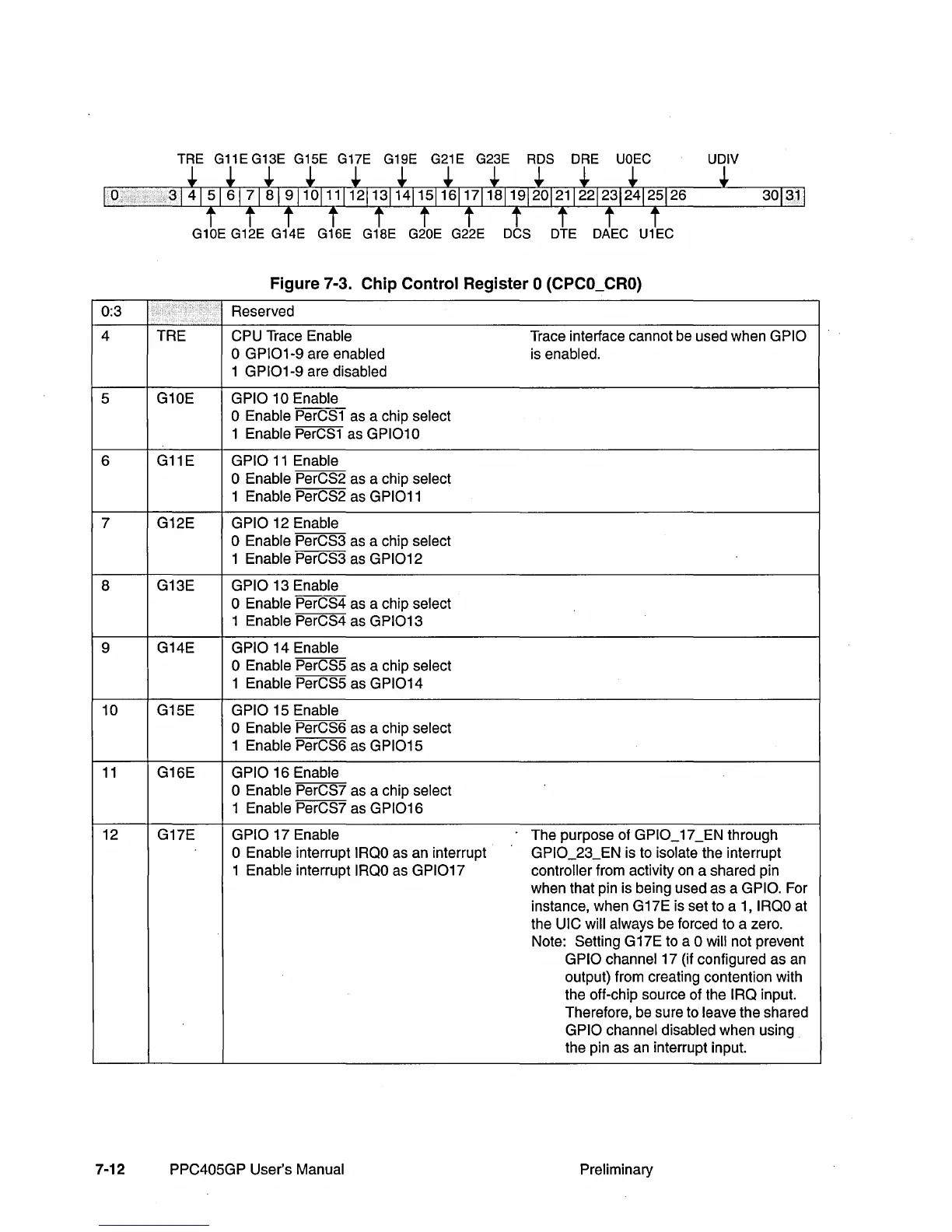
Figure 7-3. Chip Control Register 0 (CPCO_CRO)
0:3
Reserved
4 TRE
CPU Trace Enable
Trace interface cannot
be
used when GPIO
o
GPI01-9
are enabled is enabled.
1
GPI01-9
are disabled
5 G10E
GPIO 10 Enable
o Enable
PerCS1
as
a chip select
1 Enable
PerCS1
as
GPI010
6
G11E
GPIO
11
Enable
o Enable PerCS2 as a chip select
1 Enable
PerCS2 as GPI011
7 G12E GPIO 12 Enable
o Enable PerCS3
as
a chip select
1 Enable
PerCS3 as GPI012
8
G13E GPIO 13 Enable
o Enable PerCS4 as a chip select
1 Enable
PerCS4 as
GPI013
9
G14E
GPIO 14 Enable
o Enable PerCS5 as a chip select
1 Enable
PerCS5 as
GPI014
10 G15E GPIO 15 Enable
o Enable PerCS6
as
a chip select
1 Enable
PerCS6 as GPI015
11
G16E GPIO 16 Enable
o Enable PerCS7 as a chip select
1 Enable
PerCS7 as
GPI016
12 G17E GPIO 17 Enable The purpose of GPIO_17_EN through
o Enable interrupt
IROO
as
an interrupt GPIO_23_EN is to isolate the interrupt
1 Enable interrupt
IROO
as
GPI017
controller from activity
on
a shared pin
when that pin is being used as a
GPIO. For
instance, when G17E is set to a 1,
IROO
at
the
UIC will always be forced to a zero.
Note: Setting G17E to a
0 will not prevent
GPIO channel 17 (if configured as
an
output) from creating contention with
the off-chip source of the
IRa
input.
Therefore,
be
sure to leave the shared
GPIO channel disabled when using
the pin as
an
interrupt input.
7-12
PPC405GP User's Manual Preliminary

 Loading...


