DMA
Controller
PLB
....
...
....
...
....
...
....
...
OPB
----------
EBC
Controlled
lIDs
----------
Configuration
....
...
and
.....
".
Status
OCR Bus
Registers
....
....
....
....
....
....
....
~
....
....
....
....
~
....
~
.....
..
~
..
~
...
P'
..
P'
..
~
..
~
_
...
P'
...
P'
...
..
..
::.
".
..
P'
...
..
..
~
..
DMAReqO
DMAAckO
EOTO[TCO]
DMAReq1
DMAAck1
EOT1[TC1]
DMAReq2
DMAAck2
EOT2[TC2]
DMAReq3
DMAAck3
EOT3[TC3]
PerClk
PerDataO:31
PerParO:3
PerR/W
PerOE
PerWE
PerWBEO:3
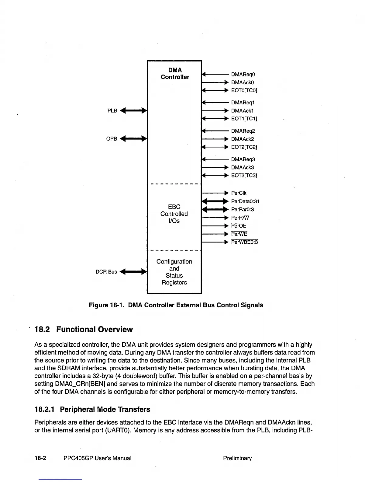
Figure 18·1. DMA Controller External Bus Control Signals
18.2 Functional Overview
As a specialized controller, the DMA unit provides system designers and programmers with a highly
efficient method of moving data. During any DMA transfer the
controller always buffers data read from
the source prior to writing the data to the destination.
Since many buses, including the internal PLB
and the
SDRAM interface, provide substantially better performance when bursting data, the DMA
controller includes a 32-byte
(4
doubleword) buffer. This buffer is enabled on a per-channel basis by
setting DMAO_CRn[BEN] and serves to minimize the number of discrete memory transactions. Each
of
the four DMA channels is configurable for either peripheral
or
memory-to-memory transfers.
18.2.1 Peripheral Mode Transfers
Peripherals are either devices attached to the EBC interface via the DMAReqn and DMAAckn lines,
or
the internal serial port (UARTO). Memory is any address accessible from the PLB, including PLB-
18-2
PPC405GP
User's
Manual
Preliminary