IOU
SME
+
+
1
0
415
91
10
1
11
31
1
t
IOL
Figure 18-3. DMA Sleep Mode Register (DMAO_SLP)
0:4
IDU Idle Timer Upper Upper 5-bits of the idle timer.
0-31
5:9
IDL Idle Timer Lower Lower 5-bit portion of the idle timer.
Hardcoded to
Ob11111
Writing this field has no effect.
10
SME
Sleep Mode Enable If SME=1, also set CPMO_ER[DMA] to
o Sleep disabled
enable the Clock and Power
1
Sleep enabled
Management macro to put the DMA
controller to sleep.
11
:31
Reserved
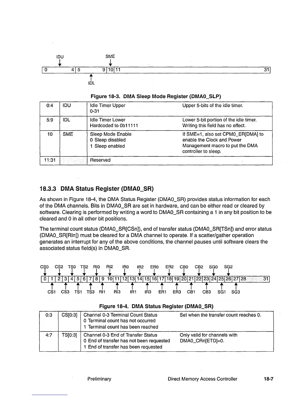
18.3.3 DMA Status Register (DMAO_SR)
As shown
in
Figure 18-4, the DMA Status Register (DMAO_SR) provides status information for each
of the DMA channels. Bits
in
DMAO_SR are set
in
hardware, and can be either read or cleared by
software. Clearing is performed by writing a word to DMAO_SR containing a 1
in
any bit position to be
cleared and
°
in
all other bit positions.
The terminal count status (DMAO_SR[CSn]), end of transfer status (DMAO_SR[TSn]) and error status
(DMAO_SR[Rln]) must be cleared for a DMA channel to operate.
If a scatter/gather operation
generates an interrupt for any of the above conditions, the channel pauses until software clears the
associated status field(s)
in
DMAO_SR.
CS1
CS3
TS1
TS3
RI1
RI3
IR1
IR3
ER1
ER3
CB1
CB3
SG1
SG3
Figure 18-4. DMA Status Register (DMAO_SR)
0:3
CS[0:3] Channel 0-3 Terminal Count Status Set when the transfer count reaches
O.
o Terminal count has not occurred
1 Terminal count has been reached
4:7
TS[0:3] Channel 0-3 End of Transfer Status Only valid for channels with
o End of transfer has not been requested DMAO_CRn[ETD]=O.
1 End
of
transfer has been requested
Preliminary Direct Memory Access Controller
18-7