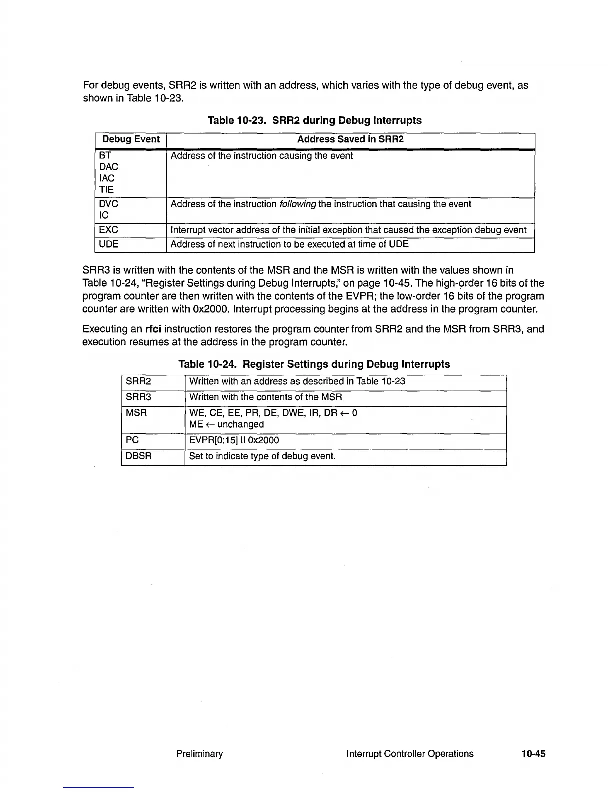
For debug events, SRR2 is written with an address, which varies with the type of debug event, as
shown
in
Table 10-23.
Table 10-23. SRR2
during
Debug Interrupts
Debug
Event
Address
Saved
in
SRR2
BT
Address of the instruction causing the event
DAC
lAC
TIE
DVC
Address of the instruction following the instruction that causing the event
IC
EXC
Interrupt
vector address of the initial exception that caused the exception debug event
UDE Address of next instruction to be executed at time of UDE
SRR3 is written with the contents of the MSR and the MSR is written with the values shown in
Table
10-24, "Register Settings during Debug Interrupts," on page 10-45. The high-9rder 16 bits of the
program counter are then written with the contents of the EVPR; the low-order 16 bits of the program
counter are written with
Ox2000. Interrupt processing begins at the address in the program counter.
Executing an
rfci
instruction restores the program counter from SRR2 and the MSR from SRR3, and
execution resumes at the address
in
the program counter.
Table 10-24. Register Settings
during
Debug Interrupts
SRR2
Written with an address as described
in
Table 10-23
SRR3
Written with the contents of the MSR
MSR
WE,
CE,
EE,
PR, DE, DWE, IR, DR
~
0
ME
~
unchanged
PC
EVPR[O:
15]11
Ox2000
DBSR
Set
to indicate type of debug event.
Preliminary Interrupt Controller Operations 10-45