o
CE
PR ME
OWE
OR
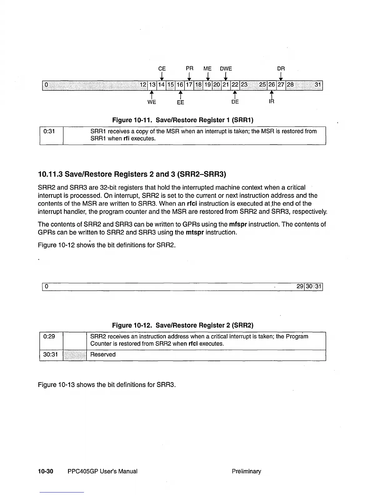
Figure 10-11. Save/Restore Register 1 (SRR1)
SRR1 receives a copy of the MSR when an interrupt is taken; the MSR is restored from
SRR1
when rfi executes.
10.11.3 Save/Restore Registers 2 and 3 (SRR2-SRR3)
SRR2 and SRR3 are 32-bit registers that hold the interrupted machine context when a critical
interrupt is processed. On interrupt, SRR2 is set to the current or next instruction address and the
contents of the
MSR are written to SRR3. When an rfci instruction is executed at.the end of the
interrupt
handler, the program counter and the MSR are restored from SRR2 and SRR3, respectively.
The contents of SRR2 and SRR3 can be written to GPRs using the mfspr instruction. The contents of
GPRs can be written to
SRR2 and SRR3 using the mtspr instruction.
Figure
10-12 shows the bit definitions for SRR2.
1
0
Figure 10-12. Save/Restore Register 2 (SRR2)
0:29 SRR2 receives
an
instruction address when a critical interrupt is taken; the Program
Counter is restored from SRR2 when
rfci executes.
30:31 Reserved
.
Figure 10-13 shows the bit definitions for SRR3.
10-30 PPC405GP User's Manual Preliminary