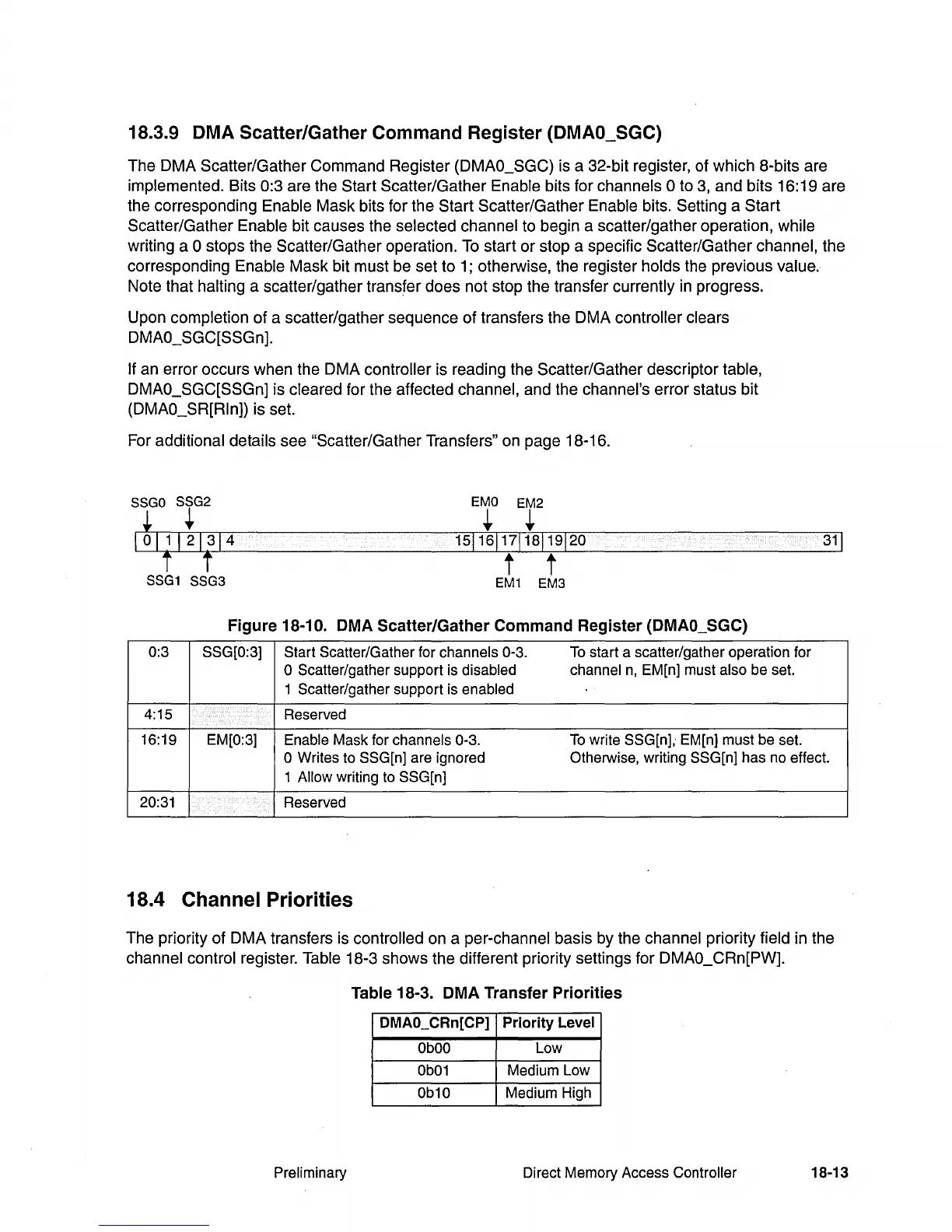
18.3.9 DMA Scatter/Gather Command Register (DMAO_SGC)
The DMA Scatter/Gather Command Register (DMAO_SGC) is a 32-bit register, of which 8-bits are
implemented. Bits 0:3 are the Start Scatter/Gather Enable bits for channels ° to
3,
and bits 16:19 are
the corresponding
Enable Mask bits for the Start Scatter/Gather Enable bits. Setting a Start
Scatter/Gather
Enable bit causes the selected channel to begin a scatter/gather operation, while
writing a ° stops the Scatter/Gather operation.
To
start
or
stop a specific Scatter/Gather channel, the
corresponding
Enable Mask bit must be set to
1;
otherwise, the register holds the previous value.
Note that halting a scatter/gather transfer does not stop the transfer currently
in
progress.
Upon
completion of a scatter/gather sequence of transfers the DMA controller clears
DMAO_SGC[SSGn].
If
an error occurs when the DMA controller is reading the Scatter/Gather descriptor table,
DMAO_SGC[SSGn]
is cleared for the affected channel, and the channel's error status bit
(DMAO_SR[Rln]) is set.
For
additional details see "Scatter/Gather Transfers" on page 18-16.
SSGO
SSG2
~
...
EMO
EM2
...
...
t t
SSG1
SSG3
15116117118119120
t t
EM1
EM3
Figure 18-10. DMA Scatter/Gather Command Register (DMAO_SGC)
0:3
SSG[0:3] Start Scatter/Gather for channels 0-3.
To
start a scatter/gather operation for
o Scatter/gather support is disabled channel
n,
EM[n] must also be set.
1 Scatter/gather support is
enabled
4:15 Reserved
16:19 EM[0:3]
Enable Mask for channels 0-3.
To
write SSG[n],· EM[n] must be set.
31
1
o Writes to SSG[n] are ignored Otherwise, writing SSG[n] has no effect.
1
Allow writing to SSG[n]
20:31
Reserved
18.4 Channel Priorities
The priority of DMA transfers is controlled on a per-channel basis by the channel priority field in the
channel control register. Table 18-3 shows the different priority settings for DMAO_CRn[PW].
Table 18-3. DMA Transfer Priorities
DMAO_CRn[CP]
Priority
Level
ObOO
Low
Ob01
Medium Low
Ob10
Medium High
Preliminary Direct Memory Access Controller
18-13