External Bus
Controller
PLB
....
...
....
....
External Master
Arbitration
and
Controls
- - -
--
~
...
Configuration
....
r
Registers
OCR Bus
...
..
..
..
....til
_
....
~
~
~
:-
.....
~
...
...
....
....
~
...
....
...
~
...
.....
r
...
...
...
..
....
...
~
....
~
....
..
~
....
..
...
_
...
..
....
....
..
...
PerClk
ExtReset
PerAddrO:31
PerDataO:31
PerParO:3
PerCSO
PerCS1 :7[GPI01
0:16]
PerRIW
PerWBEO:3
PerOE
PerWE[PCIINT]
PerBLast
PerReady
PerErr
HoldReq
HoldPri
HoldAck
BusReq
ExtReq
ExtAck
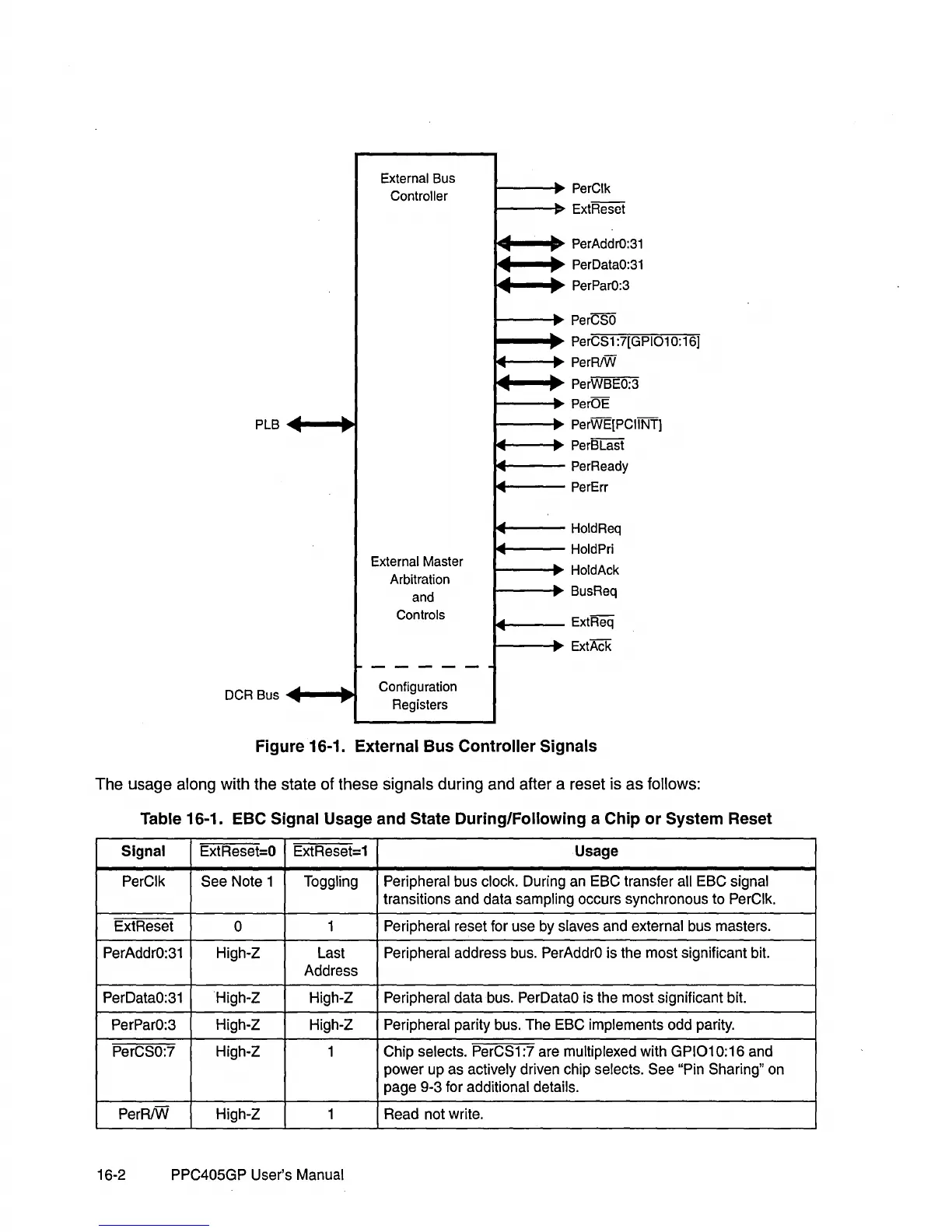
Figure 16-1. External Bus Controller Signals
The usage along with the state of these signals during and after a reset is as follows:
Table 16-1. EBC Signal Usage and State During/Following a Chip
or
System Reset
Signal ExtReset=O ExtReset=1 Usage
PerClk See Note 1
Toggling Peripheral bus clock. During an ESC transfer all ESC signal
transitions and data sampling occurs synchronous to PerClk.
ExtReset
0
1
Peripheral reset for use by slaves and external bus masters.
PerAddrO:31 High-Z Last
Peripheral address bus. PerAddrO is the most significant bit.
Address
PerDataO:31 High-Z High-Z
Peripheral data bus. PerDataO is the most significant bit.
PerParO:3
High-Z High-Z
Peripheral parity bus. The ESC implements odd parity.
PerCSO:7
High-Z
1
Chip selects. PerCS1:7 are multiplexed with GPI010:16 and
power up as
actively driven chip selects. See "Pin Sharing" on
page 9-3 for
additional details.
PerRIW High-Z 1 Read not write.
16-2 PPC405GP User's
Manual