10.11.1 Machine State Register (MSR)
The MSR is a 32-bit register that holds the current context of the PPC405GP. When a noncritical
interrupt is taken, the MSR contents are written to SRR1; when a critical interrupt is taken, the MSR
contents are written to SRR3. When
an
rfi
or
rfci instruction executes, the contents of the MSR are
read from SRR1
or
SRR3, respectively.
Programming Note: The rfi and rfci instructions can alter reserved MSR fields.
The MSR contents can be read into a general purpose register (GPRs) using an mfmsr instruction.
The contents of a GPR can be written to the MSR using an
mtmsr instruction. The MSR[EE] bit may
be
set/cleared atomically using the wrtee
or
wrteei instructions.
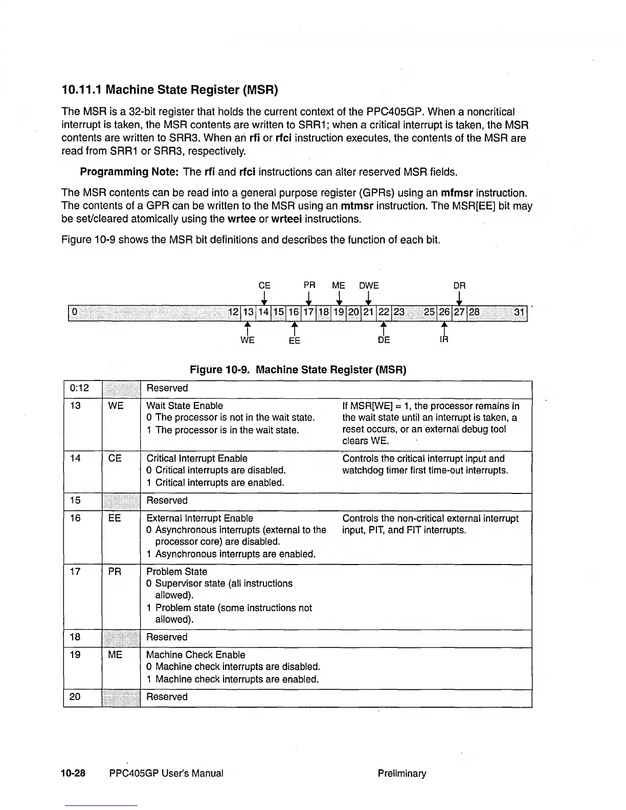
Figure 10-9 shows the MSR bit definitions and describes the function of each bit.
CE
PR
ME
OWE
DR
o
Figure 10-9. Machine State Register (MSR)
0:12
Reserved
13
WE
Wait State
Enable
If MSR[WE] =
1,
the processor remains
in
o The processor is not
in
the wait state.
the wait state until an interrupt is taken, a
1 The processor is
in
the wait state.
reset occurs, or an
external debug tool
clears
WE.
14 CE
Critical Interrupt Enable
Controls the critical interrupt input and
o Critical interrupts are disabled.
watchdog timer first time-out interrupts.
1
Critical interrupts are enabled .
15
",
..
Reserved
16 EE
External Interrupt Enable Controls the non-critical external interrupt
o Asynchronous interrupts (external to the input,
PIT,
and FIT interrupts.
processor core) are
disabled.
1 Asynchronous interrupts are enabled.
17
PR
Problem State
o Supervisor state (all instructions
allowed).
1 Problem state (some instructions not
allowed) .
18
I
..
"
..
Reserved
•
.....
19 ME
Machine Check Enable
o Machine check interrupts are disabled.
1 Machine check interrupts are enabled.
20
I ,
..
"
•••••.
I,··
..
·,.
Reserved
10-28 PPC405GP User's Manual
Preliminary