15.3.3 Memory
Bank
0-3
Configuration (SDRAMO_BOCR-SDRAMO_B3CR)
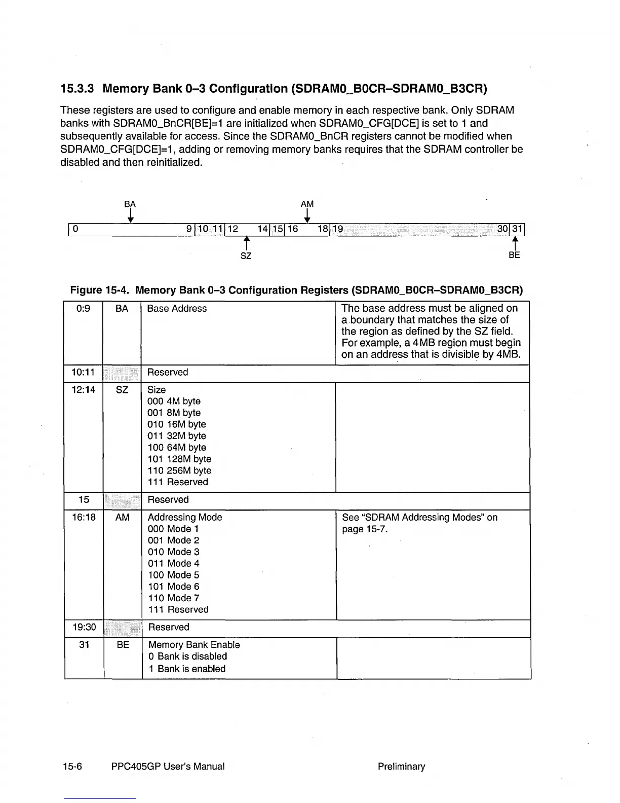
These
registers
are
used to configure and enable
memory
in each respective bank.
Only
SDRAM
banks
with SDRAMO_BnCR[BE]=1 are initialized
when
SDRAMO_CFG[DCE] is set to 1
and
subsequently available for access. Since the SDRAMO_BnCR registers cannot
be
modified
when
SDRAMO_CFG[DCE]=1, adding
or
removing
memory
banks requires that the
SDRAM
controller be
disabled
and
then reinitialized.
BA
AM
+ +
911011112
14115116
18119
1
0
t
t
sz
BE
Figure 15-4. Memory Bank
0-3
Configuration Registers (SDRAMO_BOCR-SDRAMO_B3CR)
0:9
BA
Base Address
The
base address
must
be aligned on
a.boundary
that matches the size
of
the region
as
defined by the
SZ
field.
For example, a
4MB
region
must
begin
on
an
address that is divisible
by
4MB.
10:11
Reserved
12:14
SZ
Size
000
4M
byte
001
8M
byte
010
16M
byte
011
32M
byte
100
64M
byte
101
128M byte
110 256M byte
111
Reserved
15
Reserved
16:18
AM
Addressing Mode
See
"SDRAM
Addressing Modes"
on
000 Mode 1 page 15-7.
001
Mode 2
010 Mode 3
011
Mode 4
100 Mode 5
101
Mode 6
110 Mode 7
111
Reserved
19:30 Reserved
31
BE
Memory Bank Enable
o Bank
is
disabled
1 Bank
is
enabled
15-6 PPC405GP User's Manual Preliminary