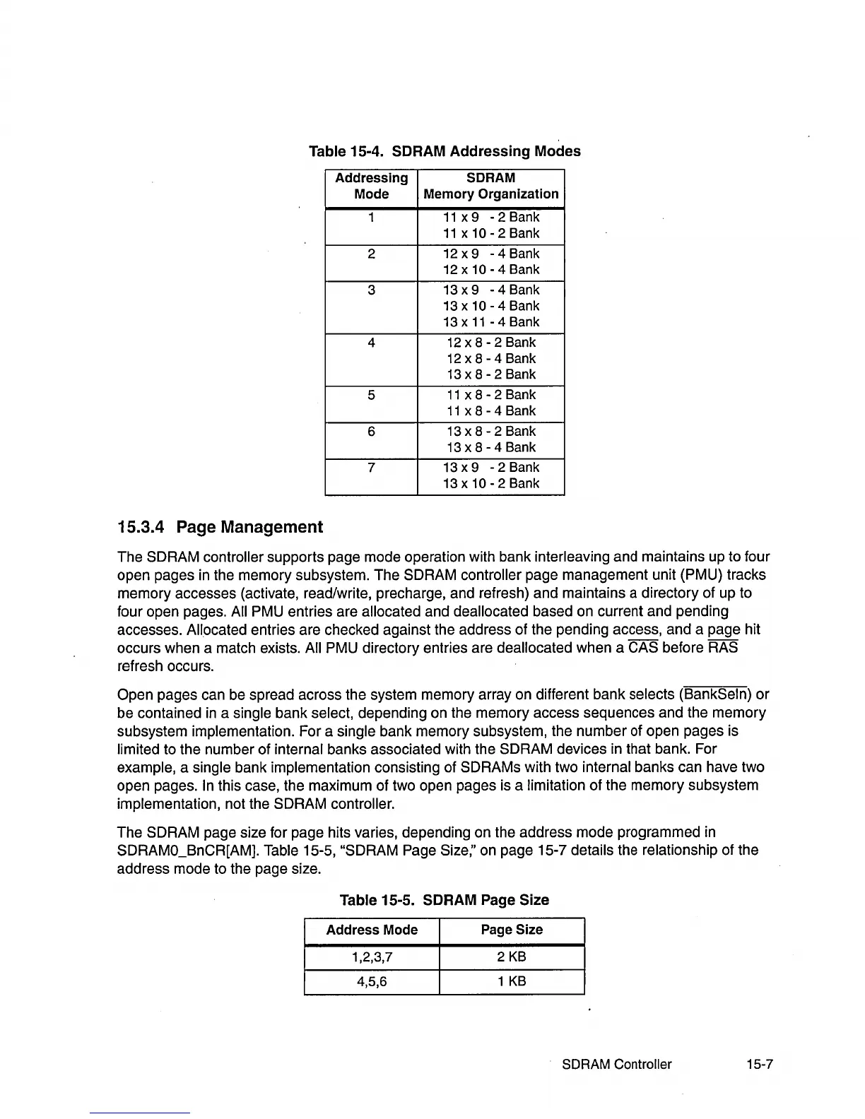
Table 15-4. SCRAM Addressing Modes
Addressing
SCRAM
Mode
Memory
Organization
1
11
x 9 - 2 Bank
11
x 10 - 2 Bank
2
12 x 9 - 4 Bank
12x10-4Bank
3
13 x 9 - 4 Bank
13x10-4Bank
13 x
11
- 4 Bank
4
12
x 8 - 2 Bank
12
x 8 - 4 Bank
13 x 8 - 2 Bank
5
11
x 8 - 2 Bank
11
x 8 - 4 Bank
6
13 x 8 - 2 Bank
13 x 8 - 4 Bank
7
13 x 9 - 2 Bank
13x10-2Bank
15.3.4 Page Management
The SDRAM controller supports page mode operation with bank interleaving and maintains up to four
open pages
in
the memory subsystem. The SDRAM controller page management unit (PMU) tracks
memory accesses (activate, read/write, precharge, and refresh) and maintains a directory of up to
four open pages.
All PMU entries are allocated and deallocated based on current and pending
accesses.
Allocated entries are checked against the address of the pending access, and a page hit
occurs when a match exists.
All PMU directory entries are deallocated when a CAS before RAS
refresh occurs.
Open pages can be spread across the system memory array on different bank selects (BankSeln)
or
be contained
in
a single bank select, depending on the memory access sequences and the memory
subsystem implementation. For a single bank memory subsystem, the number of open pages is
limited to the number of internal banks associated with the SDRAM devices
in
that bank. For
example, a single bank implementation consisting of SDRAMs with two internal banks can have two
open pages.
In this case, the maximum of two open pages is a limitation of the memory subsystem
implementation, not the SDRAM
controller.
The SDRAM page size for page hits varies, depending on the address mode programmed
in
SDRAMO_BnCR[AM). Table 15-5, "SDRAM Page Size;' on page 15-7 details the relationship of the
address mode to the page size.
Table 15-5. SCRAM Page Size
Address
Mode
Page Size
1,2,3,7
2
KB
4,5,6
1
KB
SDRAM Controller
15-7