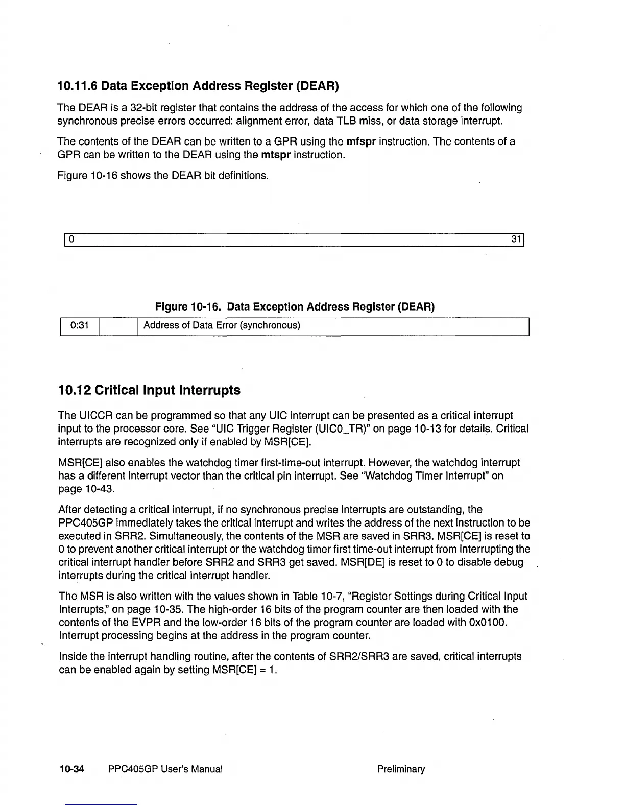
10.11.6 Data Exception Address Register (DEAR)
The DEAR is a 32-bit register that contains the address of the access for which one of the following
synchronous precise errors occurred: alignment error, data TLB miss, or data storage interrupt.
The contents of the DEAR can be written to a GPR using the
mfspr
instruction. The contents of a
GPR can be written to the DEAR using the
mtspr
instruction.
Figure
10-16 shows the DEAR bit definitions.
1
0
31
1
Figure
10-16. Data
Exception
Address
Register
(DEAR)
0:31 I Address of Data Error (synchronous)
10.12 Critical Input Interrupts
The UICCR can be programmed so that any UIC interrupt can be presented as a critical interrupt
input to the processor core.
See "UIC Trigger Register (UICO_TR)" on page 10-13 for details. Critical
interrupts are recognized only if enabled by MSR[CE].
MSR[CE] also enables the watchdog timer first-time-out interrupt. However, the watchdog interrupt
has a different interrupt vector than the
critical pin interrupt. See "Watchdog Timer Interrupt" on
page
10-43.
After detecting a critical interrupt, if no synchronous precise interrupts are outstanding, the
PPC405GP
immediately takes the critical interrupt and writes the address of the next instruction to be
executed
in
SRR2. Simultaneously, the contents of the MSR are saved
in
SRR3. MSR[CE] is reset to
o to prevent another critical interrupt or the watchdog timer first time-out interrupt from interrupting the
critical interrupt handler before SRR2 and SRR3 get saved. MSR[DE] is reset to 0 to disable debug
interrupts during the
critical interrupt handler.
The MSR is also written with the values shown in Table 10-7, "Register Settings during Critical Input
Interrupts,"
on page 10-35. The high-order 16 bits of the program counter are then loaded with the
contents of the
EVPR and the low-order 16 bits of the program counter are loaded with Ox0100.
Interrupt
processing begins at the address
in
the program counter.
Inside the interrupt handling routine, after the contents of SRR2/SRR3 are saved, critical interrupts
can be
enabled again by setting MSR[CE] =
1.
10-34
PPC405GP User's Manual Preliminary