CRO
CR2 CR4
CR6
~
*
i
i
1
0
31
4
71
8
11112
15
1
16
19
1
20 23
1
24 27
1
28
f
31
1
t
f
t
CR1
CR3
CR5
CR7
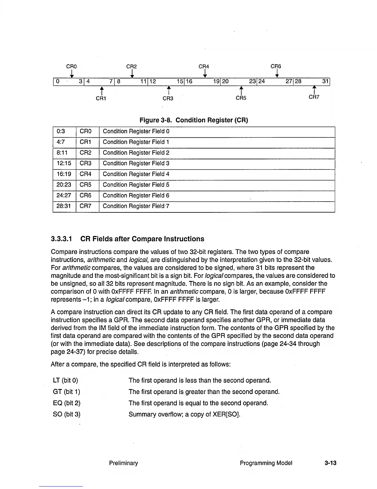
Figure 3-8. Condition Register (CR)
0:3
CRO
Condition Register Field 0
4:7
CR1
Condition Register Field 1
8:11
CR2 Condition Register Field 2
12:15
CR3 Condition Register
Field 3
16:19
CR4 Condition Register
Field 4
20:23 CR5 Condition Register Field 5
24:27
CR6 Condition Register
Field 6
28:31 CR7
Condition Register
Field
'7
3.3.3.1
CR
Fields after Compare Instructions
Compare instructions compare the values of two 32-bit registers. The two types of compare
instructions,
arithmetic and logical, are distinguished by the interpretation given to the 32-bit values.
For arithmetic compares, the values are considered to be signed, where
31
bits represent the
magnitude and the most-significant bit is a sign bit. For
logical compares, the values are considered to
be unsigned, so
all 32 bits represent magnitude. There is no sign bit. As an example, consider the
comparison of
0 with OxFFFF
FFFF.
In an arithmetic compare, 0 is larger, because OxFFFF FFFF
represents
-1;
in
a logical compare, OxFFFF FFFF is larger.
A compare instruction can direct its CR update to any CR field. The first data operand of a compare
instruction specifies a GPR. The second data operand specifies another GPR, or immediate data
derived from the
1M
field of the immediate instruction form. The contents of the GPR specified by the
first data operand are compared with the contents of the GPR specified by the second data operand
(or with the immediate data).
See descriptions of the compare instructions (page 24-34 through
page 24-37) for precise details.
After a compare, the specified
CR field is interpreted as follows:
LT
(bit 0)
GT
(bit 1)
EQ (bit 2)
SO (bit 3)
The first operand is
less than the second operand.
The first operand is greater than the second operand.
The first operand is
equal to the second operand.
Summary
overflow; a copy of XER[SO].
Preliminary
Programming Model 3-13