18.2.3 Scatter/Gather Transfers
Each of the four DMA channels supports scatter/gather transfers. This scatter/gather capability allows
the chaining of multiple DMA controller operations within a channel. During a normal DMA operation
software must program the
control, source address, destination address, and count registers for each
transfer. Scatter/gather transfers differin that these registers are automatically
loaded from a linked
list
data structure
in
system memory. When a channel completes one transfer the DMA controller
loads
the next set of configuration values into the channel's registers and the channel continues with
the new programmings.
18.3 Configuration and Status Registers
Table 18-2 on page 18-4 lists the DMA configuration and status registers, each of which is accessed
using the PowerPC
mtdcr
and
mfdcr
instructions. As example, the following PowerPC assembly
code writes the control register for DMA channel 0 and then reads the DMA status register:
#define
DMAO_CRO
OxlOO
#define
DMAO_SR
Ox120
mtdcr
mfdcr
DMAO_CRO,r3
r4,DMAO_SR
!
write
r3
to
channel
°
control
register
!
read
contents
of
status
register
into
r4
The DMA configuration and status registers are readable at any time. However, since each register
read requires a separate operation, it is not
possible to guarantee that the values read from multiple
registers correspond to a state that ever existed
in
the DMA controller.
To
illustrate, consider software
that reads the destination address for
channel 0 (DMAO_DAO) and then the count for channel 0
(DMAO_CTO).
If
the DMA controller updates the count between these two operations, the values read
differ from what is expected.
While reads can occur at any time, software must not write the configuration registers for any
channel
that is currently enabled (DMAO_CRn[CE]=1). The only exception is that a channel may be disabled
by reading the channel control register, clearing the channel enabie bit, and then writing the new
value to the control register. Once a channel is disabled, all of its configuration registers may be
reprogrammed as desired.
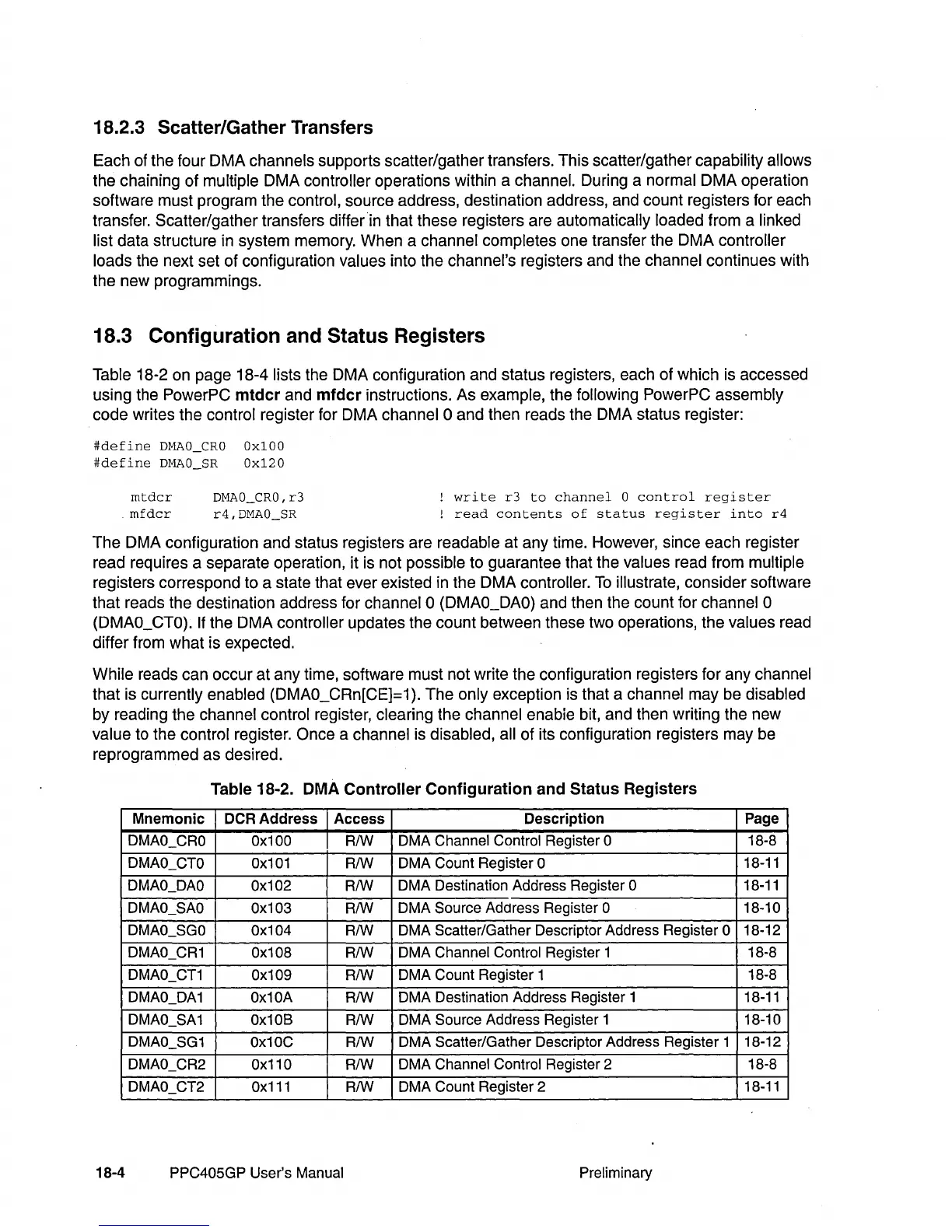
Table 18-2.
DMA
Controller
Configuration
and
Status
Registers
Mnemonic
DCRAddress Access
Description Page
DMAO_CRO
Ox100
RIW
DMA Channel Control Register 0 18-8
DMAO_CTO
Ox101
RIW DMA Count Register 0
18-11
DMAO_DAO
Ox102
RIW
DMA Destination Address Register 0 18-11
DMAO_SAO
Ox103
RIW
DMA Source Adaress Register 0
18-10
DMAO_SGO Ox104
RIW
DMA Scatter/Gather Descriptor Address Register 0 18-12
DMAO_CR1 Ox108
RIW
DMA Channel Control Register 1
18-8
DMAO_CT1 Ox109
RIW
DMA Count Register 1
18-8
DMAO_DA1 Ox10A
RIW
DMA Destination Address Register 1
18-11
DMAO_SA1 Ox10B
RIW
DMA Source Address Register 1 18-10
DMAO_SG1
Ox10C
RIW
DMA Scatter/Gather Descriptor Address Register 1 18-12
DMAO_CR2 Ox110
RIW
DMA Channel Control Register 2
18-8
DMAO_CT2
Ox111
RIW
DMA Count Register 2
18-11
18-4
PPC405GP User's Manual
Preliminary