Chapter
9.
Pin Strapping and Sharing
9.1
Pin Strapping
When power is applied to the PPC405GP, a start-up process is initiated
in
which internal functions
are
initialized. Some of these functions have optional choices. Which of the options are used for
initialization is determined by the way a specific
~et
of
liD
pins (balls) are conditioned. The
conditioning is achieved using
external pull-up (indicated as 1)
or
pull-down (indicated as 0) resistors
connected to the pins.
While the SysReset input Signal is low (system reset), the state of the lID pins is read to enable
default initial
conditions before PPC405GP start-up. The actual capture instant
is
the nearest SysClk
clock
edge before the deassertion of SysReset. The state of the pins as read is stored in the Chip Pin
Strapping Register
(CPCO_PSR) shown
in
Figure 9-1. Refer to PowerPC 405GP Embedded
Processor Data
Sheet, which describes the strapping pins.
9.1.1
Chip Pin Strapping Register (CPCO_PSR)
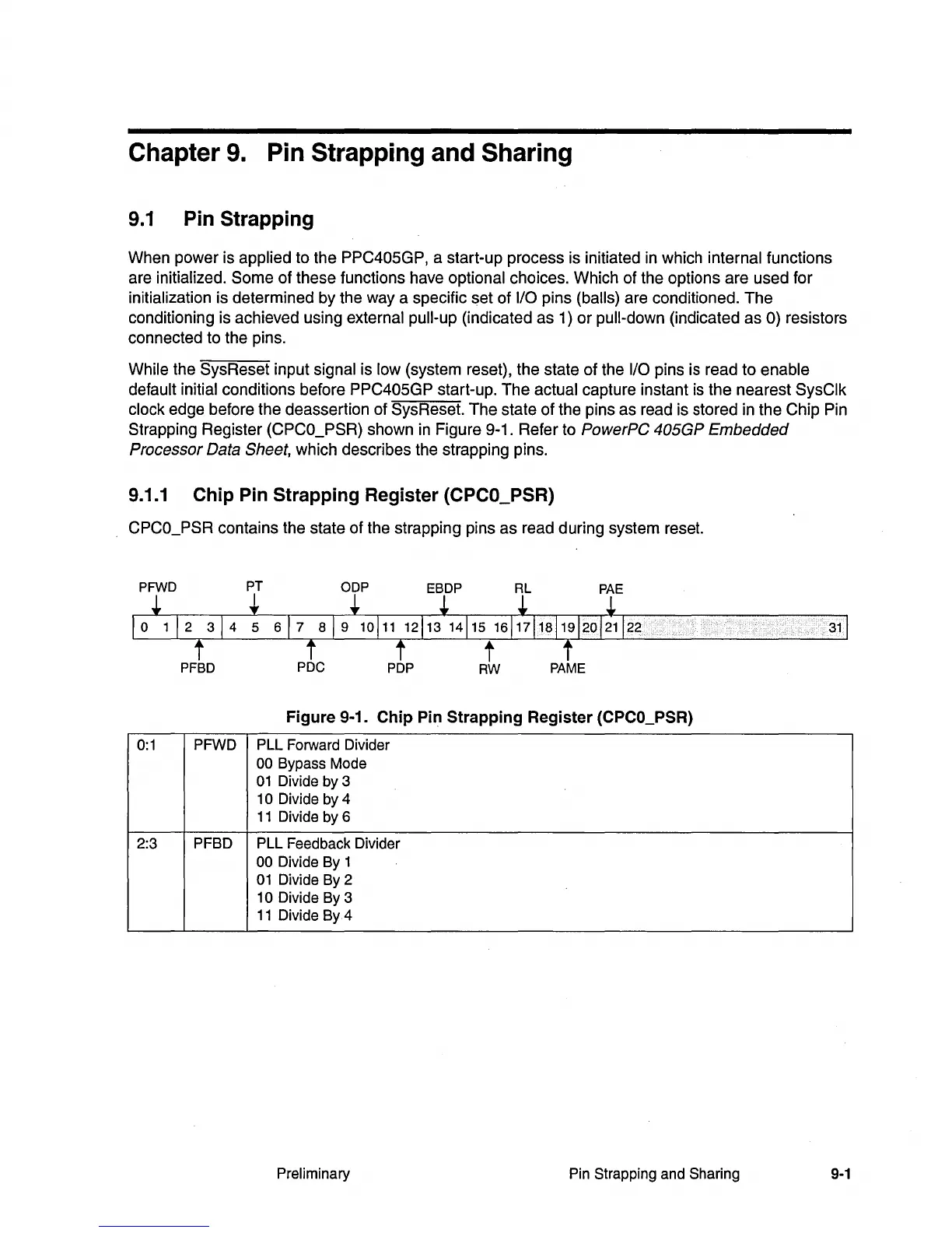
CPCO_PSR contains the state of the strapping pins as read during system reset.
31
Figure 9-1.
Chip
Pin
Strapping
Register (CPCO_PSR)
0:1
PFWD PLL Forward Divider
00 Bypass Mode
01
Divide by 3
1
0 Divide by 4
11
Divide by 6
2:3
PFBD PLL Feedback Divider
00 Divide By 1
01
Divide By 2
10 Divide By 3
11
Divide By 4
Preliminary Pin Strapping and Sharing 9-1