events are enabled by setting the appropriate DAC enable DBCR1 [D2R,D2W] to cause an address
comparison and by setting any bit combination in the DBCR1
[DV1
BE]. Each bit in DBCR1
[DV1
BE,
DV2BE] correspondes to a byte
in
DVC1
and DVC2. Exact address compare and range address
compare work the same for DVC as for a
simple DAC.
DBSR[DR1] and DBSR[DW1] record status for
DAC1
debug events. Which DBSR bit is set depends
on the setting
of
DBCR1
[D1
R)
and DBCR[D1 W]. If DBCR1
[D1
R]
=
1,
DBSR[DR1] = 1, assuming that
a DVC event occurred.
Similarly, if DBCR1
[D1
W] =
1,
DBSR[DW1] = 1, assuming that a DVC event
occurred.
Similarly, DBSR[DR2) and DBSR[DW2] record status for DAC2 debug events. Which DBSR bit is set
depends on the setting of DBCR1 [D2R] and DBCR[D2W).
If DBCR1 [D2R] =
1,
DBSR[DR2] = 1,
assuming that a DVC event occurred.
Similarly, if DBCR1 [D2W] =
1,
DBSR[DW2] =
1,
assuming that
a DVC event occurred.
In
the following example, a
DVC1
event is enabled setting the DBCR1
[D1
R]
= 1, DBCR1 [D1W] = 1,
DBCR1 [DA 12]
=
0,
and DBCR1
[DV1
BE'
0000]. When the data address and data \Blue match the
DAC1
and
DVC1
,a
DVC1
event is recorded in DBSR[DR1) or DBSR[DW1], depending on whether
the operation is a
load (read) or a store (write). This example corresponds to the last line of
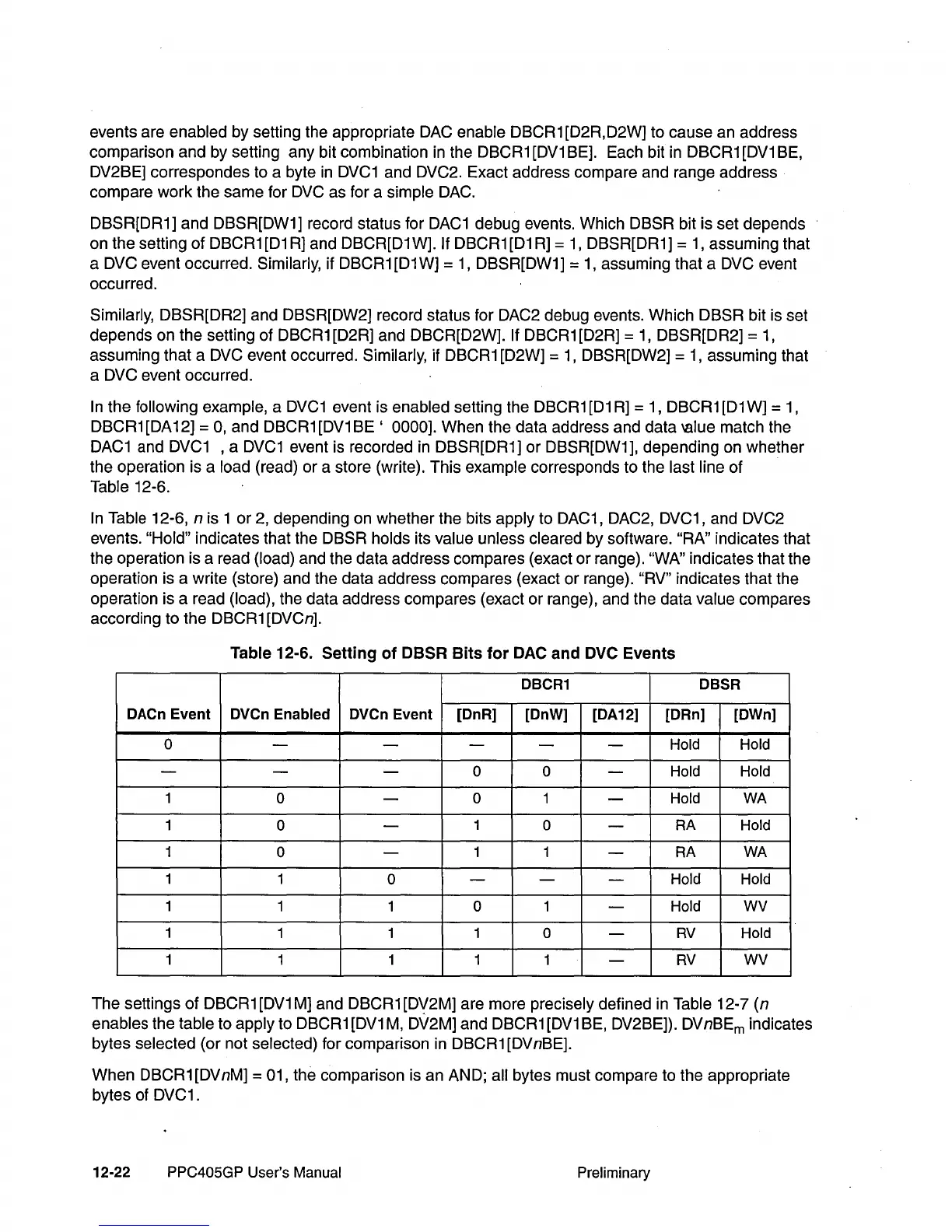
Table 12-6.
In
Table 12-6, n is 1
or
2, depending on whether the bits apply to DAC1, DAC2, DVC1, and DVC2
events.
"Hold" indicates that the DBSR holds its value unless cleared by software. "RA" indicates that
the operation is a read
(load) and the data address compares (exact
or
range). "WA" indicates that the
operation is a write (store) and the data address compares (exact or range).
"RV" indicates that the
operation is a read
(load), the data address compares (exact or range), and the data value compares
according to the DBCR1 [DVCn].
Table 12-6. Setting
of
OBSR
Bits
for
OAC
and
OVC
Events
OBCR1 OBSR
OACn
Event
OVCn
Enabled
OVCn
Event
[OnR] [OnW] [OA12]
lORn]
[OWn]
0
-
-
-
-
-
Hold Hold
-
- -
0 0
-
Hold Hold
1
0
-
0 1
-
Hold
WA
1
0
-
1
0
-
RA
Hold
1
0
-
1 1
-
RA
WA
1
1
0
- - -
Hold Hold
1
1 1
0 1
-
Hold
WV
1
1 1 1
0
-
RV
Hold
1 1 1 1
1
-
RV
WV
The settings
of
DBCR 1
[DV1
M] and DBCR 1 [DV2M] are more precisely defined in Table 12-7 (n
enables the table to apply to DBCR1
[DV1
M,
D\/2M] and DBCR1
[DV1
BE, DV2BE]). DVnBEm indicates
bytes
selected (or not selected) for comparison in DBCR1 [DVnBE].
When DBCR1 [DVnM]
= 01, the comparison is an AND; all bytes must compare to the appropriate
bytes of DVC1.
12-22
PPC405GP User's Manual
Preliminary