Scan Recipes - Creating and Editing a Scan Recipe KLA-Tencor P-16+ / P-6 User’s Guide
3-64 KLA-Tencor Confidential 0142530-000 AB
3/13/09
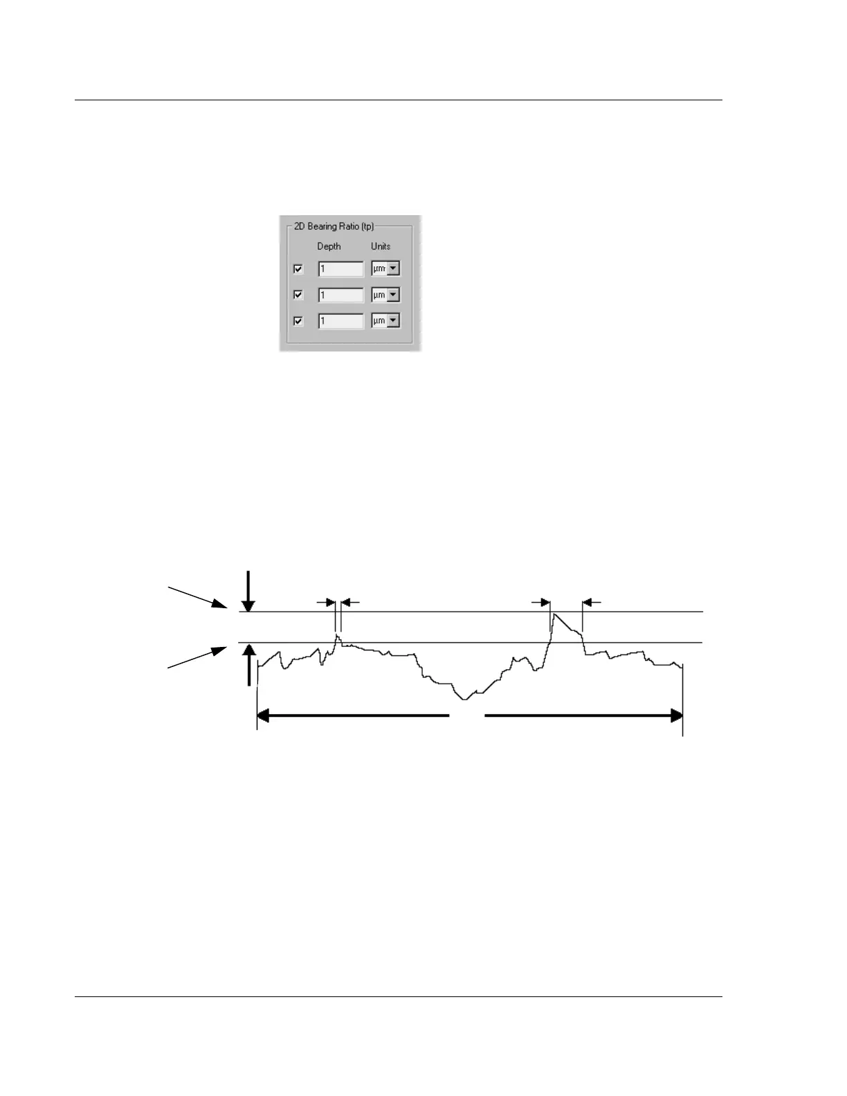
1. The option exists to create three 2D bearing ratio parameters. Click in up to
three empty checkboxes to put a check (9) in them and activate their variable
boxes. (See Figure 3.48.)
2. The depth is set down from the highest peak in the scan. It can be set in either
microns (
μm) or angstroms (Å). Determine which units are going to be used and,
if a change is necessary, click the menu arrow under units to display its menu.
3. Click the desired unit signifier,
μm or Å.
4.
Depth is the distance down from the top of the highest point in the scan. To set or
change the
Depth, double-click the current Depth variable and type in the new
depth. (See Figure 3.49.)
2D Cutting Depth (CutDp) 3
Cutting Depth is related to Bearing Ratio in that Bearing Ratio uses an operator set
depth from the top peak in the scan, adding up the points between the top peak and the
set depth, while
Cutting Depth uses an operator set ratio of data points in the scan that
are below the highest peak in the scan, causing the system to determine the depth.
(See the definition of Bearing Length Ratio in Bearing Ratio (tp) on page 3-63.)
Use the following procedure to set the 2D Cutting Depth variables.
Figure 3.48 2D Bearing Ratio
Figure 3.49 Depth for 2D Bearing Ratio
L
(Sampling Length)
S
2
S
1
Depth
Highest point
in the scan.
Depth: Set a number of
μm or Å down from the
highest point.