Calibrations - Scan Position Offset Calibration KLA-Tencor P-16+ / P-6 User’s Guide
12-6 KLA-Tencor Confidential 0142530-000 AB
3/13/09
14. Click the same feature again in exactly the same place on the feature as the first
click.
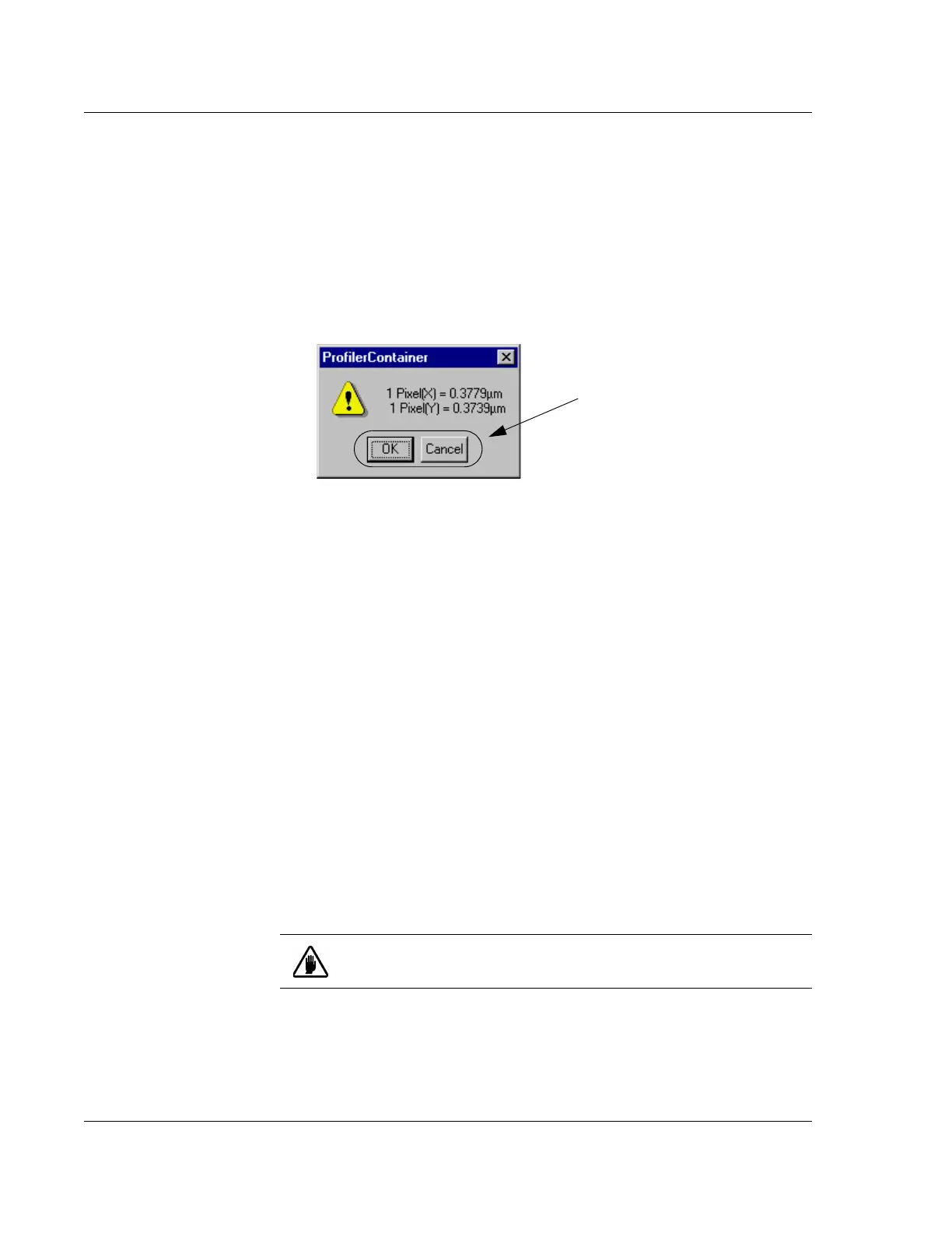
The Profiler Container message box is displayed (this is true also if the pattern
recognition finds the chosen pattern after Step 11 on page -5).
The calibration results are presented as calculated ratios of:
vertical and horizontal screen units called pixels to X and Y stage
coordinates in microns (a ratio of Pixels to microns, see Figure 12.6.)
15. Click
OK to save the calibration or Cancel to reject it and retain the old
calibration. The
Calibration screen is then displayed. (See Figure 12.6.)
SCAN POSITION OFFSET CALIBRATION 12
Introduction 12
The Scan Position Offset Calibration procedure scans for data that it then uses to
calculate the X-, Y-axis offsets from the optics and stylus, for positioning the sample
stage.
During the Stylus Change procedure, the system automatically sets up the Scan
Position Offset Calibration to be performed as part of the procedure.
See the "Scan Position Offset Calibration" , starting on Page 13-9, for the scan
position offset calibration procedure.
STEP HEIGHT CALIBRATION 12
Check the Calibration
Matrix on page 12-1 for
possible interaction with
other calibrations.
The vertical sensing transducers in the system are not absolute devices and, therefore,
require calibration.
Figure 12.6 XY Video Display Message Box
Step 15 Click OK to save the
calibration or
Cancel to reject it and
retain the old calibration.
CAUTION: All vertical ranges must be calibrated. Each calibration
must be performed independently.