Scan Recipes - Creating and Editing a Scan Recipe KLA-Tencor P-16+ / P-6 User’s Guide
3-24 KLA-Tencor Confidential 0142530-000 AB
3/13/09
Traces
This assigns the number of scans that are made in the X-direction across the
Y Scan
Size
direction. In Figure 3.19, the number in the Traces variable box would be 8.
If the
Y Scan Size is set [Y Scan Size = (Traces -1) x Y Spacing], when the Traces:
parameter is entered, the
Y Spacing parameter automatically adjusts to reflect the
appropriate spacing between scans.
Setting the Number of
Traces: To change the number of Traces in a 3D scan,
highlight the current
Traces value and type in the new number of traces. (See also
Automatic Parameter Adjustment: in Y Spacing (mm) on page 3-24.)
Y
Spacing (μm)
This variable sets the distance in the Y-direction between X-direction scan traces in a
3D scan. The spacing is very important to final 3D data collection set because,
together with the stylus radius, it determines the essential resolution of the feature that
is scanned.
Consider to following example: If the distance between scans is too great with respect
to the stylus radius, important variations in the scanned feature might be missed.
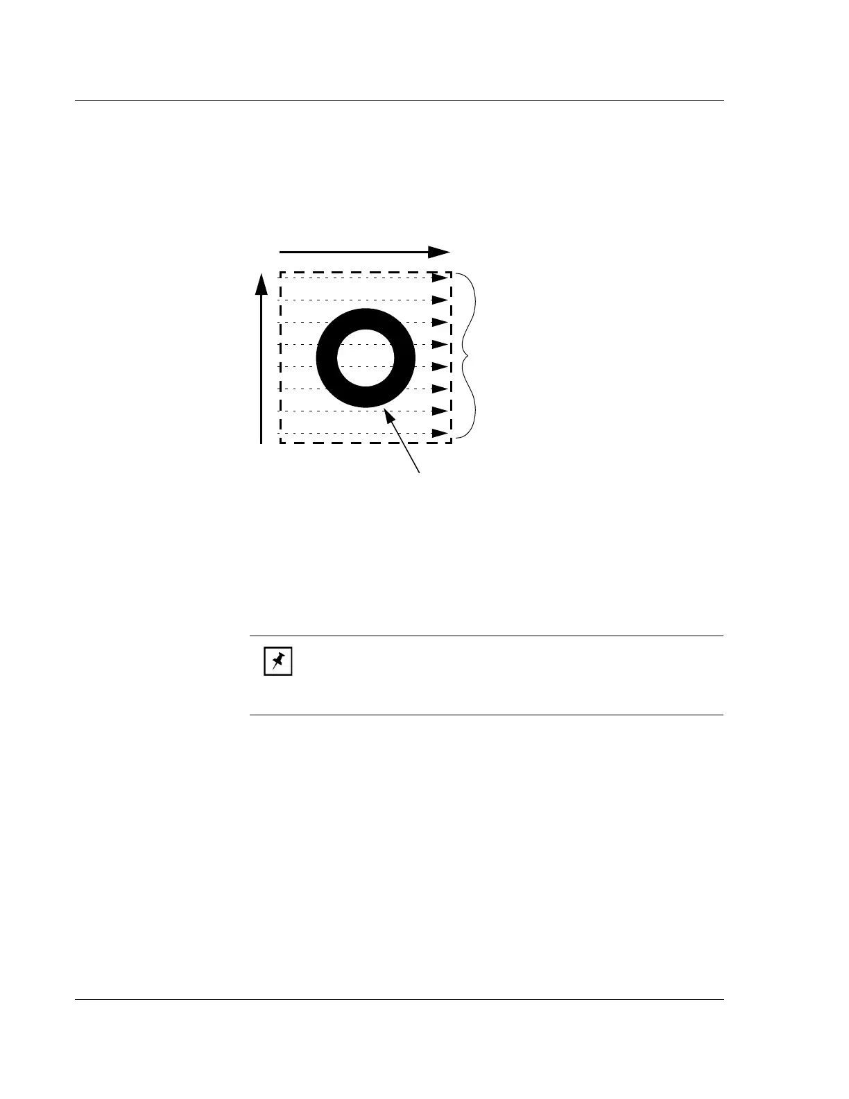
Figure 3.19 Traces - Scan Perimeter with Traces
X Scan Size
Y Scan Size
This scan contains 8 traces,
illustrated as dotted line arrows.
The number of traces is defined
in the
Traces parameter.
Feature being scanned
NOTE: The first trace occurs at y = 0 µm. Setting the number of
traces to an odd number ensures that the y-spacing will be an even
number. For example, a 100 µm y-size and 11 traces produces 10 µm
between each trace.