0142530-000 AB KLA-Tencor Confidential 3-47
3/13/09
KLA-Tencor P-16+ / P-6 User’s Guide Scan Recipes - Creating and Editing a Scan Recipe
3. Click Filters/Cursors to display the Filters and Cursors parameters.
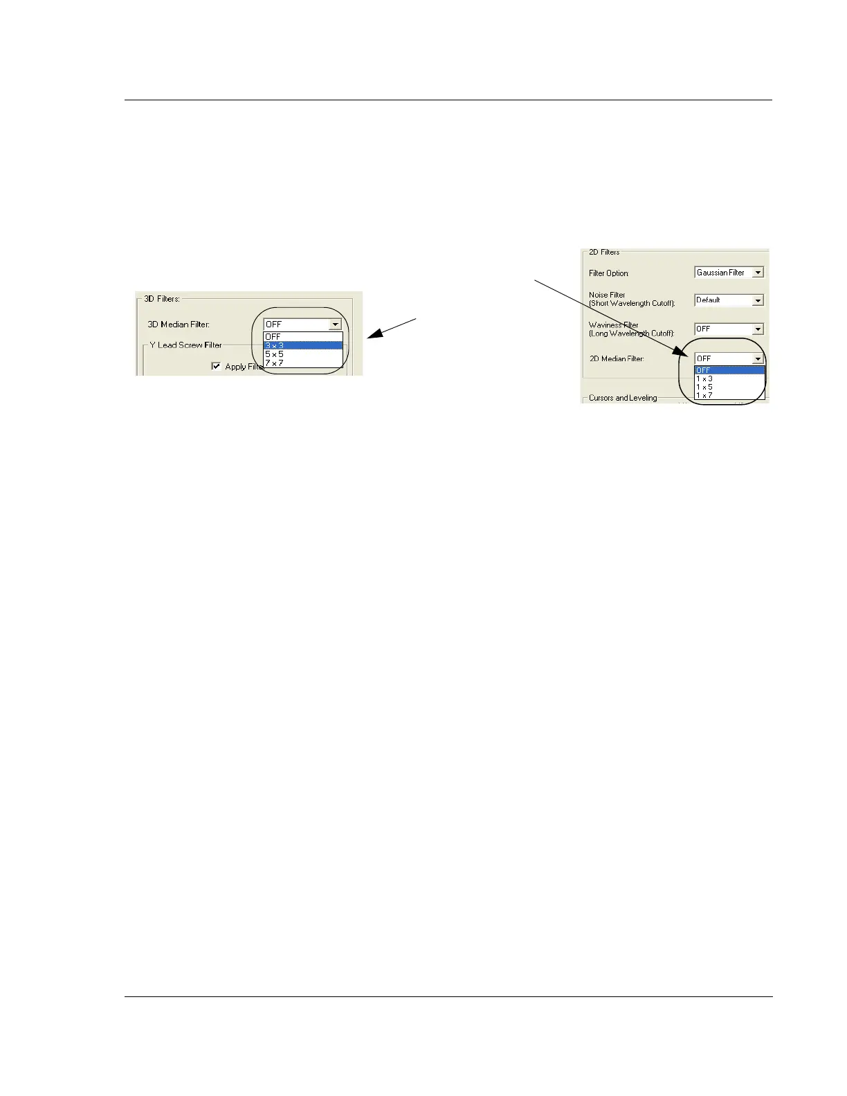
4. Click the menu-arrow for either the 2D or 3D Median Filter to display the
options. (See Figure 3.37.)
5. Choose the required filter size for the 2D or 3D data.
6. Click the Analysis screen icon in the tool bar to return to the Analysis screen for
the affected data.
For additional use of the median filter, see “Activate 3D Glitch Removal Tool.” on
page 15.
Y Lead Screw Filter 3
This filter can be used only with large 3D scans. The Y Lead Screw Filter is designed
to remove the Y lead screw noise present in die level 3D scan data.
The Y lead screw noise is a periodic sine wave in the data, due to the coupling of
stage motion in the Y direction together with the Y lead screw motion into the
measured Z Value.
The Y Lead Screw Filter uses a Fast Fourier Transform (FFT) function to find the
amplitude and the phase of the sine wave in the data. The period is already known,
defined by the Y lead screw hardware. A plane with the sine wave amplitude, phase,
and period is then generated and subtracted from the data.
Y Lead Screw Filter Constraints
For the Y Lead Screw Filter to be effective, the Y-direction scan length and the noise
wavelength must meet the following conditions:
Y-direction scan length
≥ Wavelength x 2, and
Y spacing ≤ Wavelength ÷ 4
When entering values in the parameter fields the Filter Width should be smaller than 3
wavelengths to avoid distortion. The default (0.9) is recommended.
Figure 3.37 2D and 3D Median Filter Options
2D Median Filter options.
3D Median Filter options