0142530-000 AB KLA-Tencor Confidential 14-23
3/13/09
KLA-Tencor P-16+ / P-6 User’s Guide Configuration - Precision Locators (P-16+ Only)
Adjusting the Disk Size: 14
1. Remove the screws (2-56×1/2 in.) securing each of the three disk supports.
2. Position each disk support to the required disk size. The five disk sizes are
identified by concentric circles on the locator surface, with the representative
disk size printed over each circle. The are three disk support mounting holes
associated with each disk size. (See Figure 14.21.)
3. Insert the screws and loosely tighten, leaving some play in the position of each
disk support. Place a representative disk on the supports and adjust them so that
the disk is supported snugly between the three supports. The final positioning of
the disk should resemble that illustrated in Figure 14.24.
4. When the three disk supports are adjusted, tighten the three disk support screws
and recheck the disk position. Leave enough clearance to take into account
manufacturing tolerances so that all disks of this size fit. Try to get the disk
centered around the central hub of the locator.
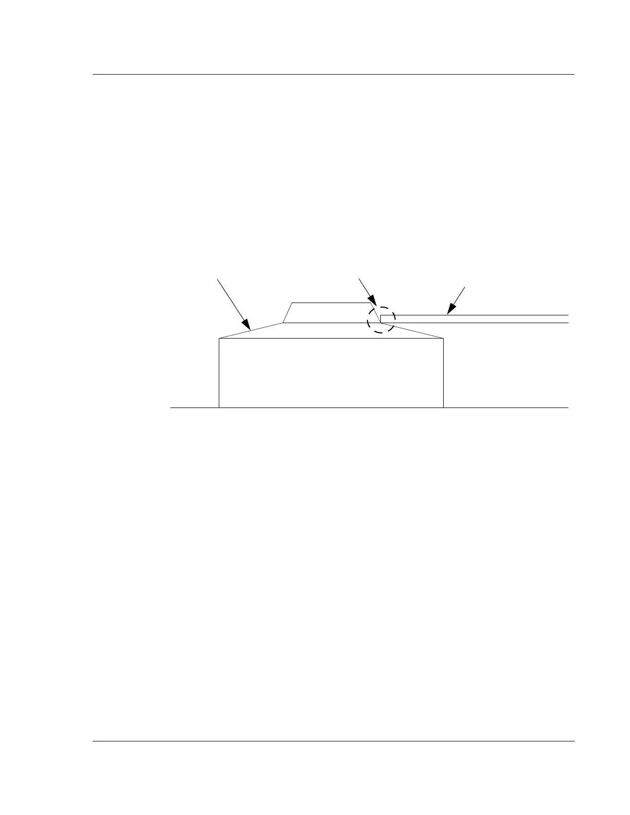
Figure 14.24 Disk Support for the Three Point Disk Locator
Disk, supported by the
Disk Support.
The disk should be
supported as shown on all
three supports.
Disk support
surface.