0142530-000 AB KLA-Tencor Confidential 3-49
3/13/09
KLA-Tencor P-16+ / P-6 User’s Guide Scan Recipes - Creating and Editing a Scan Recipe
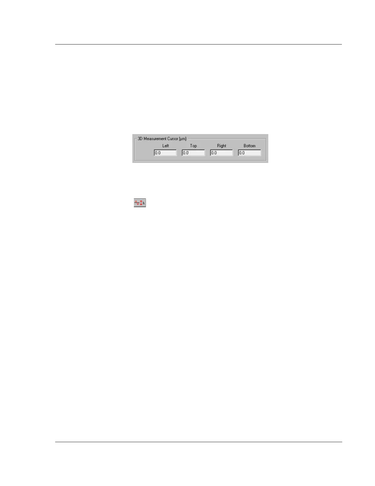
3D Measurement Cursor 3
The 3D measurement cursor is used to isolate an area of the scan, from which the
measurements designated in the recipe for inclusion in the Analysis data (such as
some of the parameters in General Parameters on page 51 and Roughness and
Waviness Parameters on page 55), can be reported. If no numbers are entered in the
3D Measurement Cursor variable boxes to define the measurement area, the data is
compiled for the entire scan area.
Setting the Cursors: Click and Drag
Cursor Positioning Using
Click-and-Drag
The 3D Measurement Cursor box is associated with the Activate Height Tool button
in the Analysis screen tool bar. In the Analysis screen, if the Activate Height
Tool button is clicked on, a box appears that can be resized and moved using the
click-and-drag method. As the box is drug around the scan image, the height of all
data points in the box is averaged with respect to sample plane and reported under
Height in the analysis statistics at the left side of the screen.
Set the Box Position in the
3D Measurement Cursor
Variable Boxes
After the box is sized and positioned, its position can be entered in the 3D
Measurement Cursor variable boxes.
1. Click the
CALC icon in the toolbar or click Operations in the menu bar
2. Choose
Recalc, to recalculate the parameters and place the cursor locations in
the 3D Measurement Cursor variable boxes.
Setting the Cursors: Manually Entering Coordinates
Manually setting the cursors is accomplished by entering the coordinate position of
the intended measurement box (Active Height Tool) directly into the
3D Measurement
Cursors
variable boxes.
X Start Level 3
This option is used to level the 3D scan with respect to the X starting position of the
scan. It assumes that the entire X=0 length of the scan is on the same plane, having no
holes or steps. If this box is checked, the other options are not used in the leveling
process. This option only levels in one direction, with respect to the X=0 plane.
To activate the
X Start Level option, click in the empty checkbox next to X Start Level.
(See Figure 3.40.)
The 3D scan progresses with each initial trace data point being used for the scan
leveling in the Y direction (using the X=0 point of each scan trace).
Figure 3.39 3D Measurement Cursor Box