XY View Screen - Positioning the Scan Site KLA-Tencor P-16+ / P-6 User’s Guide
4-14 KLA-Tencor Confidential 0142530-000 AB
3/13/09
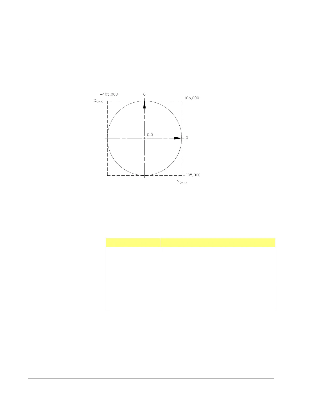
Figure 4.9 shows the stage coordinate system (SEMI Standard M20-92) used by the
Profiler. The X and Y coordinates relative to the center of the measurement area are
displayed in the current stage coordinate area of the XY View window. The travel
area of the stage is limited to a circle 210 mm (8.2 in.) in diameter. (See Figure 4.9.)
Scan Site Positioning Procedure 4
1. After the sample is loaded on the stage and the stage returned to the scan
position under the stylus, click
FOCUS.
2. Use one or more of the following methods to locate a scan site. (See Table 4.10.)
Figure 4.9 Coordinate System of the KLA-Tencor Profiler Stage
The coordinates are P-16+
max coordinates.
P-6 is 75mm in each axis.
Table 4.10 Locating a Scan Site
Movement Required Movement Method
To make a large move
across the sample
surface, use the Sample
Navigation Window
(See Figure 4.11.)
Sample Navigation Window – The navigation circle
represents the stage area. Click the location on the
Sample Navigation Window to move to the
corresponding location on the sample. (See
Figure 4.11.)
Move to a different site in
the current Video Display
Window (See
Figure 4.11.)
Video Display Window – Click the desired site in
video display window. (See Figure 4.11.)
The site moves so that the video crosshair are
centered on the chosen location.