0142530-000 AB KLA-Tencor Confidential 7-9
3/13/09
KLA-Tencor P-16+ / P-6 User’s Guide Analyzing 3D Scan Data - 3D Analysis Screen Features
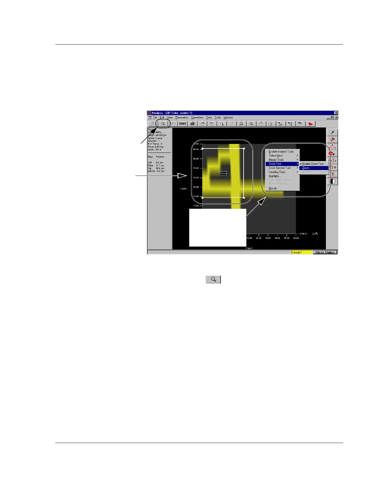
6. A good way to position the Zoom box is, click and hold on the top right handle
(boxed corner) of the
Zoom box and position it where the top right corner of the
intended zoom area. Repeat the process with the bottom left corner, placing it at
the bottom left corner of the intended zoom area. (See the intended zoom area in
Figure 7.10.)
7. When the
Zoom box is positioned as the boundary of the intended zoom area,
click the Zoom In icon in the tool bar. (See Figure 7.11.)
The 3D graphic image changes, displaying only the bounded area within the
Zoom box. (See Figure 7.12.)
ALTERNATIVE procedure for activating the zoom to display the area within
the
Zoom box:
a. Right-click to display the Right-Click menu. (See Figure 7.11.)
b. Click Zoom Tools. (See Figure 7.11.)
c. Choose Zoom. (See Figure 7.11.)
Working with a Zoomed
Image
While in the view containing the zoomed image, all the procedures contained in
the right side tool bar can be executed on the image. The Level, Slice, Height,
Step Height, and Glitch Removal, all function the same way with a zoomed
image that they do with a standard top view image.
While in the view containing the zoomed image, it is not possible to zoom in
further. To zoom in closer, return to the original image and repeat the zoom
procedure using a smaller area within the Zoom Box for the zoom image.
When the Zoom In procedure is complete, the Zoom Out icon is activated to
allow the User to return to the pre-zoom image. (See Figure 7.12.)
Figure 7.11 Analysis Screen – Using the Zoom In Icon
Zoom box relocated to the intended
Zoom area.
Step 7 Click the Zoom In icon to
zoom into the boxed area.
ALTERNATIVE to the
Zoom icon - Move
cursor to
Zoom Tools
to display its menu,
then click
Zoom.