Stylus Change Procedure - Stylus Removal and Replacement KLA-Tencor P-16+ / P-6 User’s Guide
13-18 KLA-Tencor Confidential 0142530-000 AB
3/13/09
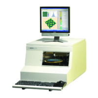
The scan can be viewed at the bottom right of the Scan: _OFF150 screen as it
progresses from left to right across the scan trace window, forming a linear
image of the scanned surface. The Start pattern next to triangle is set up to direct
the scan through the middle of the triangle using the
_OFF150 recipe. In a
perfectly calibrated system, the scan trace goes directly through the center of the
300
μm triangle creating a 150 μm trace step. However, this is not a common
occurrence for a system that has not yet been calibrated after a stylus change.
The system uses the step and the distance across the triangle to determine where
the trace was performed and then automatically calculates the offsets.
Figure 13.26 Scan: _OFF150 Window
As the scan proceeds, the trace line
progresses from left to right across
the scan trace.
As soon as the scan is complete,
the scan screen is automatically
replaced with the Analysis screen.
See Figure 13.28.
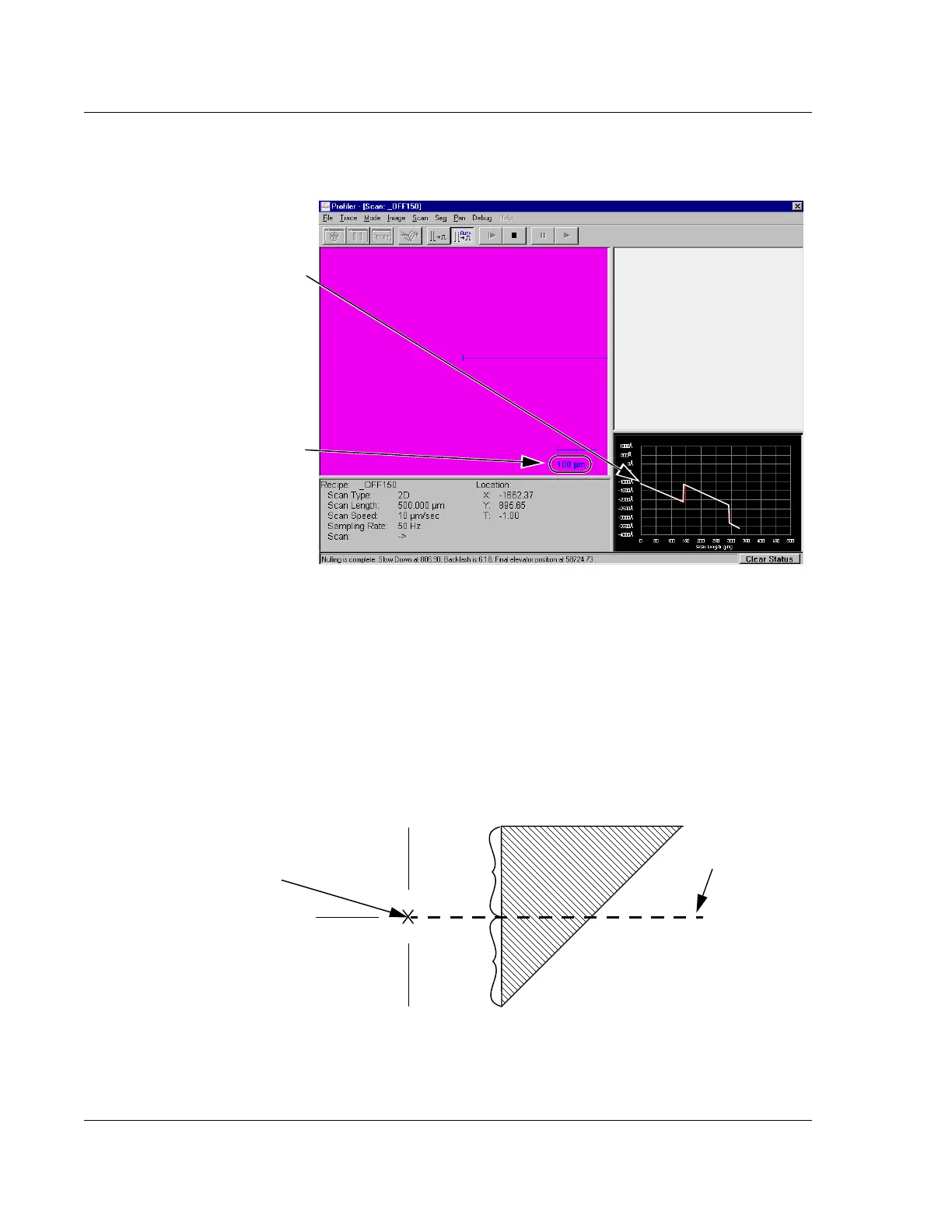
Scan calibration mark.
Figure 13.27 Trace Path Through Upper Triangle
Set the scan to begin
at the intersection of
the three lines.
150 μm
150 μm
Scan path with
150 μm step
 Loading...