Calibrations - P-16 Series Level Calibrations KLA-Tencor P-16+ / P-6 User’s Guide
12-18 KLA-Tencor Confidential 0142530-000 AB
3/13/09
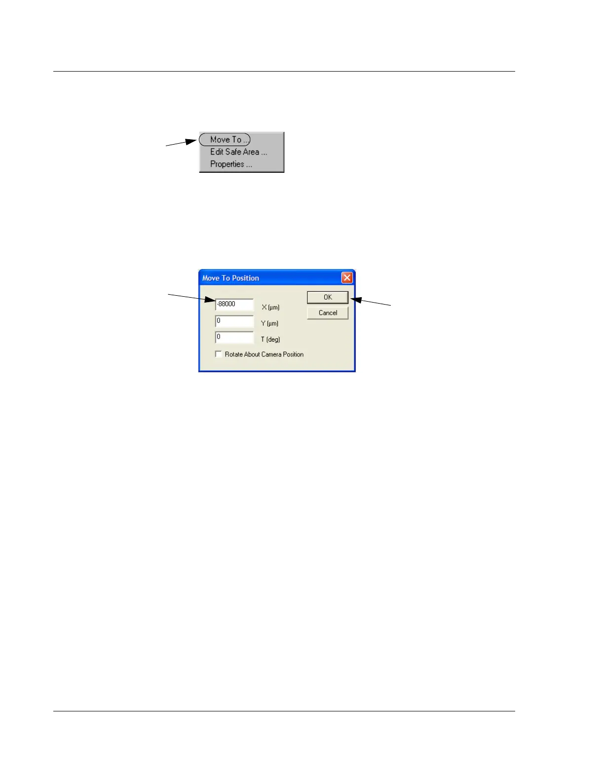
9. From the Move Menu choose Move To… (See Figure 12.21.)
10. The Move To Position dialog box opens. Leave the Y and T fields empty and
move to a coordinate approximately 10% from the right edge of the sample. For
example, when using a 200 mm wafer, enter
-88000 in the X field. (See Figure
12.22.)
11. After the entry is complete, click
OK to close the dialog box and position the
stylus at the new coordinates. (See Figure 12.22.) The blue tracking dot appears
at the left edge of the wafer.
12. After the stylus is in position, click on
FOCUS to null the stylus near the front of
wafer.
13. When the focus procedure is complete, record the
Z value as indicated in the
lower right corner of the screen. (See Figure 12.20.)
14. The numerical difference between the Z value near the right edge of the wafer
and the Z value near the left edge of the wafer represents the level calibration
results. If this number is less than 20
μm, the calibration is within specifications.
If it is not within the specifications, perform the Level calibration again and
check the results.
Figure 12.21 Move To Menu
Step 9 Choose Move
To…
to open the Move
To Position dialog box.
Figure 12.22 Move To Position Dialog Box
Step 10 Enter -88000 in
the
X field.
Step 11 Click OK to move
to the position.