User Guide 100
Managing Physical Interfaces Configuration Examples
5
Configuration Examples
5.1 Example for Port Isolation
5.1.1 Network Requirements
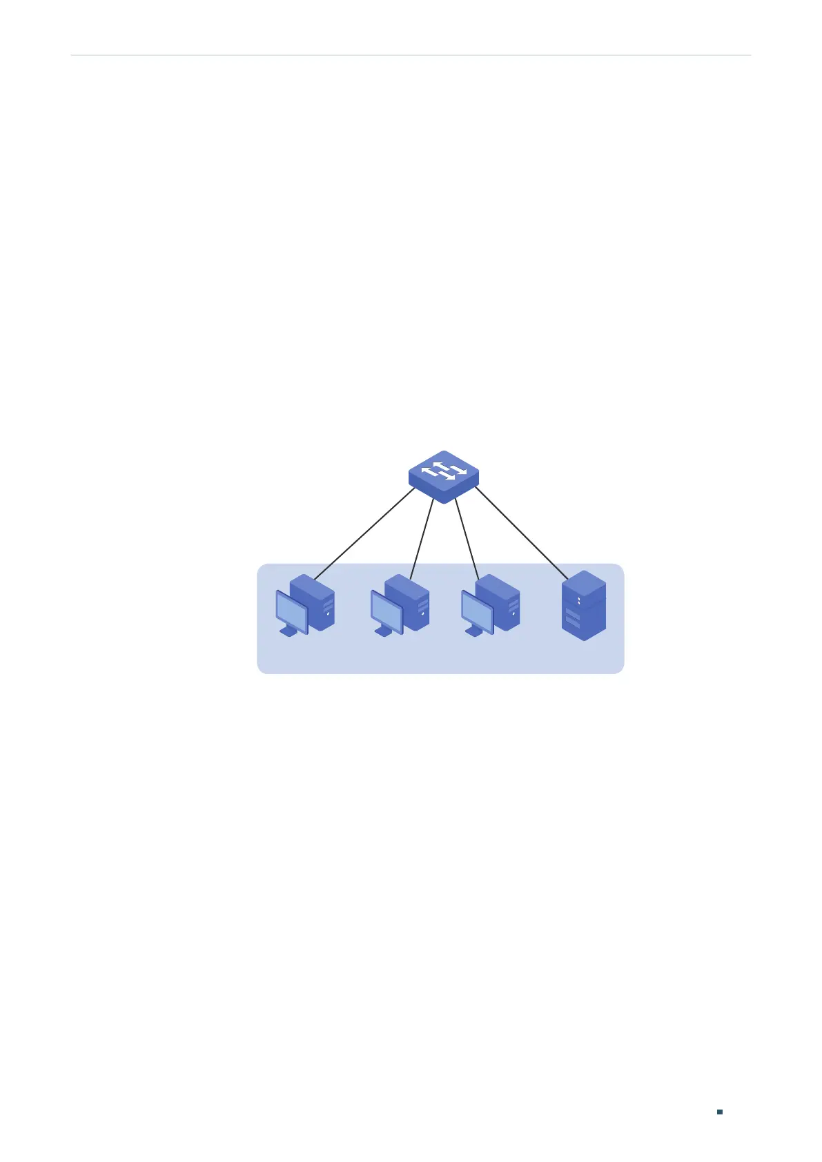
As shown below, three hosts and a server are connected to the switch and all belong to
VLAN 10. Without changing the VLAN configuration, Host A is not allowed to communicate
with the other hosts except the server, even if the MAC address or IP address of Host A is
changed.
Figure 5-1 Network Topology
VLAN 10
Switch
Gi1/0/1
Gi1/0/2
Gi1/0/4
Gi1/0/3
Host A
Host B Host C Server
5.1.2 Configuration Scheme
You can configure port isolation to implement the requirement. Set port 1/0/4 as the only
forwarding port for port 1/0/1, thus forbidding Host A to forward packets to the other
hosts.
Since communications are bidirectional, if you want Host A and the server to communicate
normally, you also need to add port 1/0/1 as the forwarding port for port 1/0/4.
Demonstrated with T2600G-28TS, the following sections provide configuration procedure
in two ways: using the GUI and using the CLI.
5.1.3 Using the GUI
1) Choose the menu L2 FEATURES > Switching > Port > Port Isolation to load the
following page. It displays the port isolation list.
 Loading...