User Guide 120
Configuring LAG Configuration Examples
R - layer3 S - layer2 f - failed to allocate aggregator
u - unsuitable for bundling w - waiting to be aggregated d - default port
Group Port-channel Protocol Ports
----- --------- ------- -------------------------------
1 Po2(S) - Gi1/0/1(D) Gi1/0/2(D) Gi1/0/3(D) Gi1/0/4(D)
Gi1/0/5(D) Gi1/0/6(D) Gi1/0/7(D) Gi1/0/8(D)
3.2 Example for LACP
3.2.1 Network Requirements
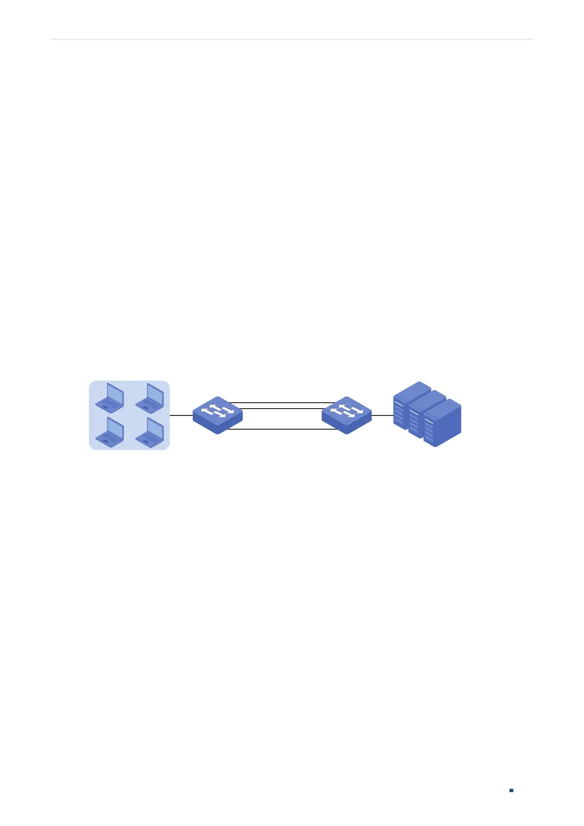
As shown below, hosts and servers are connected to switch A and switch B, and heavy
traffic is transmitted between the two switches. To achieve high speed and reliability
of data transmission, users need to improve the bandwidth and redundancy of the link
between the two switches.
Figure 3-4 Network Topology
Switch A Switch B
Hosts
Gi1/0/1 Gi1/0/1
Gi1/0/10
.
.
.
Gi1/0/10
Servers
3.2.2 Configuration Scheme
LAG function can bundle multiple physical ports into one logical interface to increase
bandwidth and improve reliability. We can configure LACP to meet the requirement.
The overview of the configuration is as follows:
1) Considering there are multiple devices on each end, configure the load-balancing
algorithm as ‘SRC MAC+DST MAC’.
2) Specify the system priority for the switches. Here we choose switch A as the dominate
device and specify a higher system priority for it.
3) Add ports 1/0/1-10 to the LAG and set the mode as LACP.
4) Specify a lower port priority for ports 1/0/9-10 to set them as the backup ports. When
any of ports 1/0/1-8 is down, the backup ports will automatically be enabled to transmit
data.
Demonstrated with T2600G-28TS, the following sections provide configuration procedure
in two ways: using the GUI and using the CLI.
 Loading...