User Guide 372
Configuring Layer 2 Multicast Configuration Examples
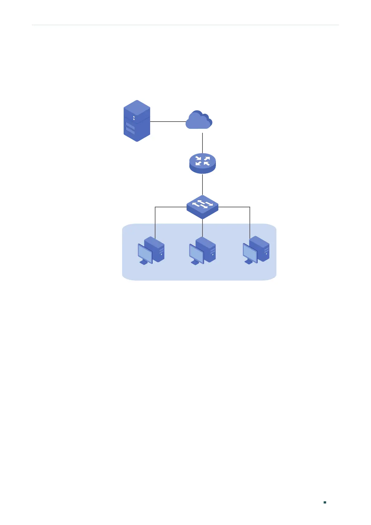
7.4.3 Network Topology
As shown in the following network topology, Host B is connected to port 1/0/1, Host C is
connected to port 1/0/2 and Host D is connected to port 1/0/3. They are all in VLAN 10.
Figure 7-18 Network Topology for Multicast Filtering
Internet
Host B
Receiver
Host C
Receiver
Host D
Receiver
VLAN 10
Querier
Source
Gi1/0/4
Gi1/0/2
Gi1/0/3
Gi1/0/1
Demonstrated with T2600G-28TS, this section provides configuration procedures in two
ways: using the GUI and using the CLI.
7.4.4 Using the GUI
1) Create VLAN 10. Add port 1/0/1-3 to the VLAN as untagged port and port 1/0/4 as
tagged port. Configure the PVID of the four ports as 10. For details, refer to Configuring
802.1Q VLAN.
2) Choose the menu L2 FEATURES > Multicast > IGMP Snooping > Global Config to load
the following page. In the Global Config section, enable IGMP Snooping globally.
 Loading...