Configuring OAM Configuration Example
User Guide
1005
4
Configuration Example
4.1 Network Requirements
A network administrator wants to manage and troubleshoot the network more effectively,
requiring that the link failure and frame errors on the link between Switch A and Switch B
can be monitored and reported via the Ethernet OAM feature.
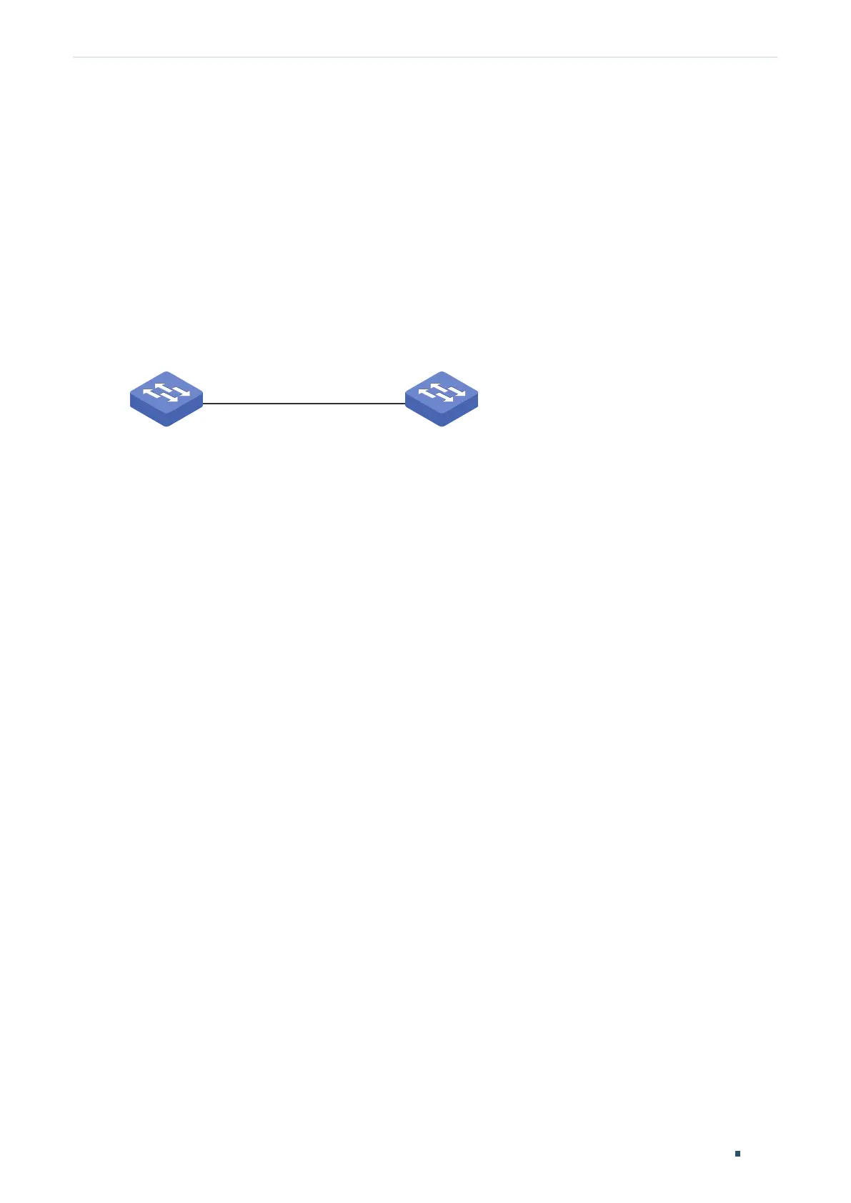
Figure 4-1 Network Topology
Switch A
Switch B
Gi1/0/1 Gi1/0/1
4.1.1 Configuration Scheme
To meet the requirement, configure OAM on port 1/0/1 of each switch. Two features can
be configured: Link Monitoring and Remote Failure Indication. With Link Monitoring, the
frame errors on the link can be monitored and reported; with Remote Failure Indication, the
link failure can be monitored and reported.
The overview of configuration is as follows:
1) Enable OAM and configure the OAM mode for port 1/0/1 on each switch. Here we
configure OAM mode of the port on Switch A as active, and that on switch B as passive.
2) Configure Link Monitoring for port 1/0/1 on each switch.
3) Configure Remote Failure Indication for port 1/0/1 on each switch.
Demonstrated with T2600G-28TS, the following sections provide configuration procedure
in two ways: using the GUI and using the CLI.
4.1.2 Using the GUI
The configurations for Switch A and Switch B are similar. We take Switch A as an example.
1) Choose the menu MAINTENANCE > Ethernet OAM > Basic Config > Basic Config to
load the following page. Select port 1/0/1, and configure the mode as Active and the state
as Enable. Click Apply.
 Loading...