Configuring L2PT Configuration Example
User Guide
491
3
Configuration Example
3.1 Network Requirements
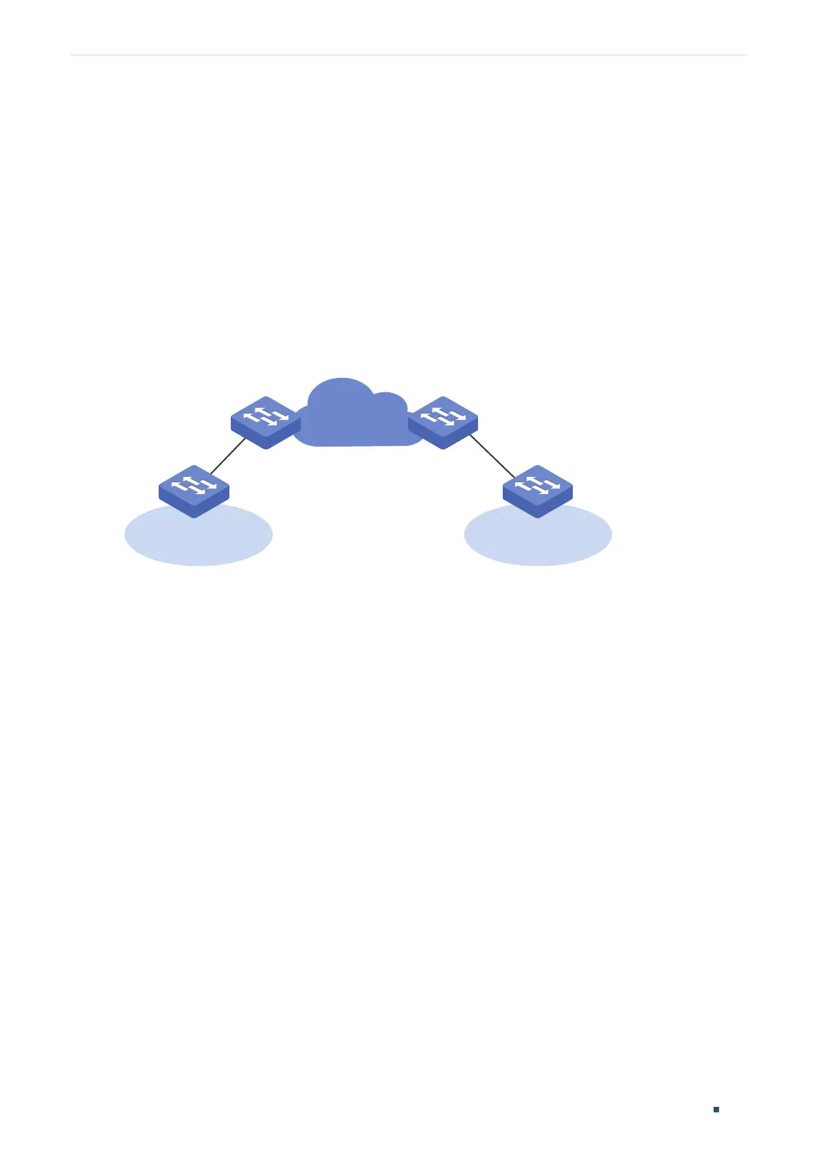
As shown below, the two branches of a company are connected through the ISP network,
and they want to achieve spanning tree calculation by exchanging Layer 2 STP packets
with each other. To meet this requirement, the ISP network needs to transparently transmit
the STP packets between the two customer networks.
Figure 3-1 Network Topology
Switch A
1/0/2
1/0/2
Switch B
Customer Network Customer Network
1/0/11/0/1
3.2 Configuration Scheme
The service provider can configure L2PT on the two edge switches (Switch A and Switch B).
With the L2PT feature, the STP packets can be encapsulated as normal data packets and
sent to the other side without being processed by the devices in the ISP network.
The overview of configuration is as follows:
1) Enable the L2PT feature globally.
2) Specify port 1/0/1 which is connected to the ISP network as an NNI port.
3) Specify port 1/0/2 which is connected to the customer network as a UNI port for the
STP. In addition, configure the threshold as 1000 to limit the number of packets to be
processed on the port in one second.
Demonstrated with T2600G-28TS, the following sections provide configuration procedure
in two ways: using the GUI and using the CLI.
3.3 Using the GUI
The configurations of Switch A and Switch B are similar. The following introductions take
Switch A as an example.
 Loading...