Issue 3.0
3-24 Installing the SV9100 Chassis
3.5 Installing the 9.5” Base (CHS2UG B-US) and Expansion
(CHS2UG E) Chassis
The CHS2UG B-US and CHS2UG E chassis combined have six universal blade
slots for legacy line/trunk blade (Single Line Telephone Interface, Digital multiline
terminal Interface, Central Office Trunk, ISDN PRI Interface, etc.), In-skin
Application Blades (In-skin UMS, In-Skin Router, etc.). It also houses the BUS
Interface Blade and Power Supply Unit (PSU).
When the GCD-CP10 blade is installed in slot 1 of the 9.5” Base Chassis, it is
called the controlling chassis. Additional chassis, (9.5” Expansion Chassis) can be
installed to increase the capacity of the system to meet the customer’s business
needs.
Before proceeding with installation of chassis, ensure site preparation is
completed. The combined chassis can be:
Wall-mounted – refer to 4.2.1.1 Wall Mounting the 9.5” Base (CHS2UG B-US)
and Expansion (CHS2UG E) Chassis on page 3-54.
Rack-mounted – refer to 7.2 Rack Mounting the 9.5” Base (CHS2UG B-US) and
Expansion (CHS2UG E) Chassis on page 3-84.
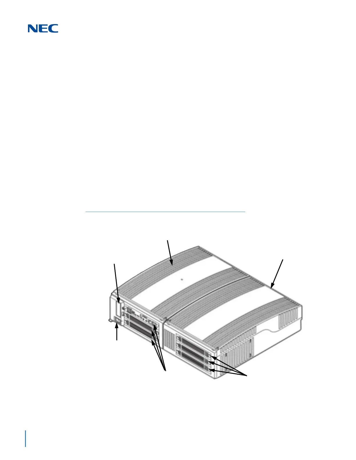
Figure 3-28 9.5”Base and Expansion (Combined) Chassis
Base Chassis
CHS2UG B-US
Expansion Chassis
CHS2UG E
GPZ-BS10 or
GPZ-BS11 Slot
Power Switch
and LED
3 Universal Slots
(Slot 1 for CPU)
3 Universal Slots

 Loading...


