Issue 3.0
SV9100 System Hardware Manual 4-83
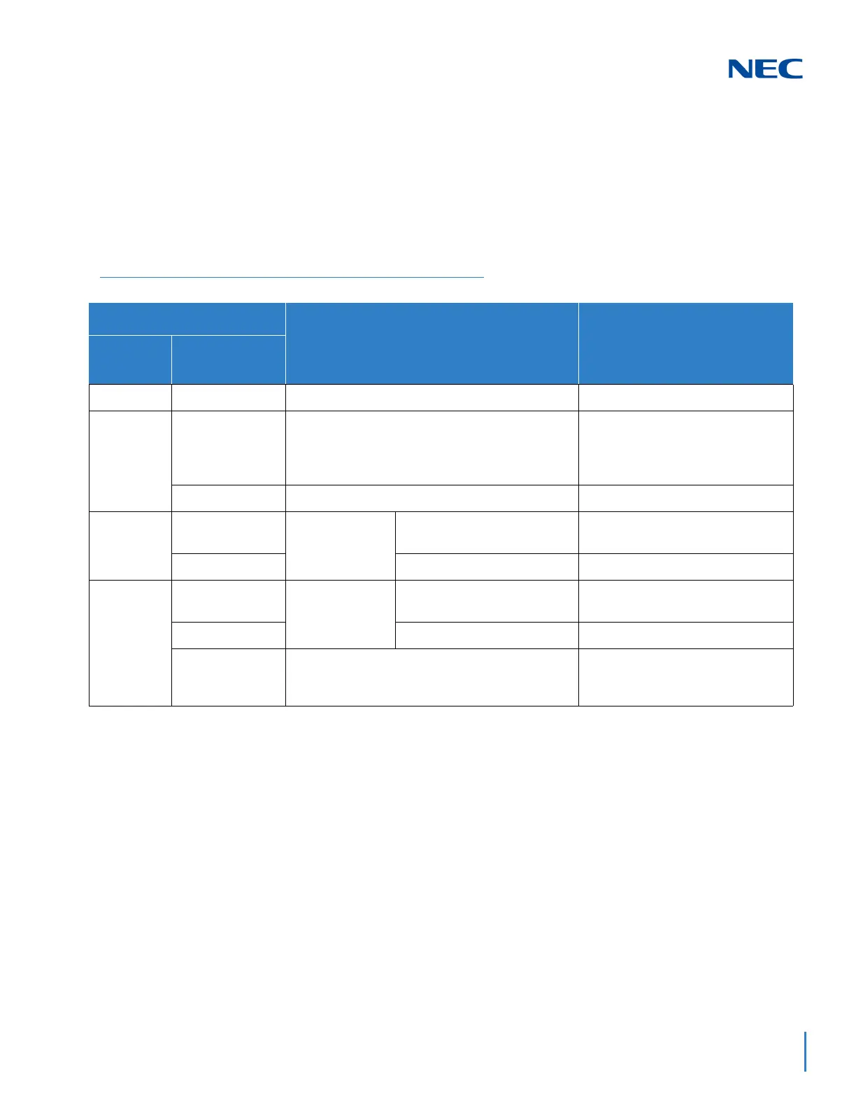
5.7.3 LED Indications
LED indications for the GCD-4ODTA are listed in Table 4-36 GCD-4ODTA
LED Indications. Each LED is listed with its associated function and LED
and Operational status.
Refer to Figure 4-29 GCD-4ODTA Blade on page 4-81 for the location of the
LEDs on the blade.
5.7.4 Connectors
Table 4-37 GCD-4ODTA RJ-61 Cable Connector Pin-Outs on page 4-84
shows the pin-outs for the RJ-61 connector. Figure 4-29 GCD-4ODTA Blade
on page 4-81 shows the location of the connectors on the ODT blade.
Table 4-36 GCD-4ODTA LED Indications
LED Indication
Operation Status Remarks
Live LED
(Green)
Busy LED (Red)
On On System Initializing
–
Flash (1s) On The assignment of the unit is refused.
When you exceed the system
capacity.
When the main software version is
not matched.
Flash (1s) Trouble found during self-diagnostics.
–
Flash
(100ms)
On
Normal
Operation
A Channel is busy (use
another from CH1 ~ CHx).
–
Off
All channels are idle. –
Off
On
Unit Busy
A Channel is busy (use
another from CH1 ~ CHx).
–
Off
All channels are idle. –
Flash 80ms (On/
Off) x 3/400ms
Off
Downloading firmware.
–

 Loading...


