Issue 3.0
SV9100 System Hardware Manual 4-35
4.1.4 Connectors
The CNx01 connectors provide connection to four digital station ports. With
the GCD-16DLCA blade, the CN101, CN201, CN301, and CN401
connectors are available. With the GCD-8DLCA blade the CN301 and
CN401connectors are removed from the blade.
Table 4-14 GCD-8DLCA/GCD-16DLCA/ RJ-61 Cable Connector Pin-Outs
on page 4-36 show the pin-outs for the RJ-61 connector. Refer to Figure
4-14 GCD-8DLCA/GCD-16DLCA Blade on page 4-33 for the location of the
connectors on the ESIU blades.
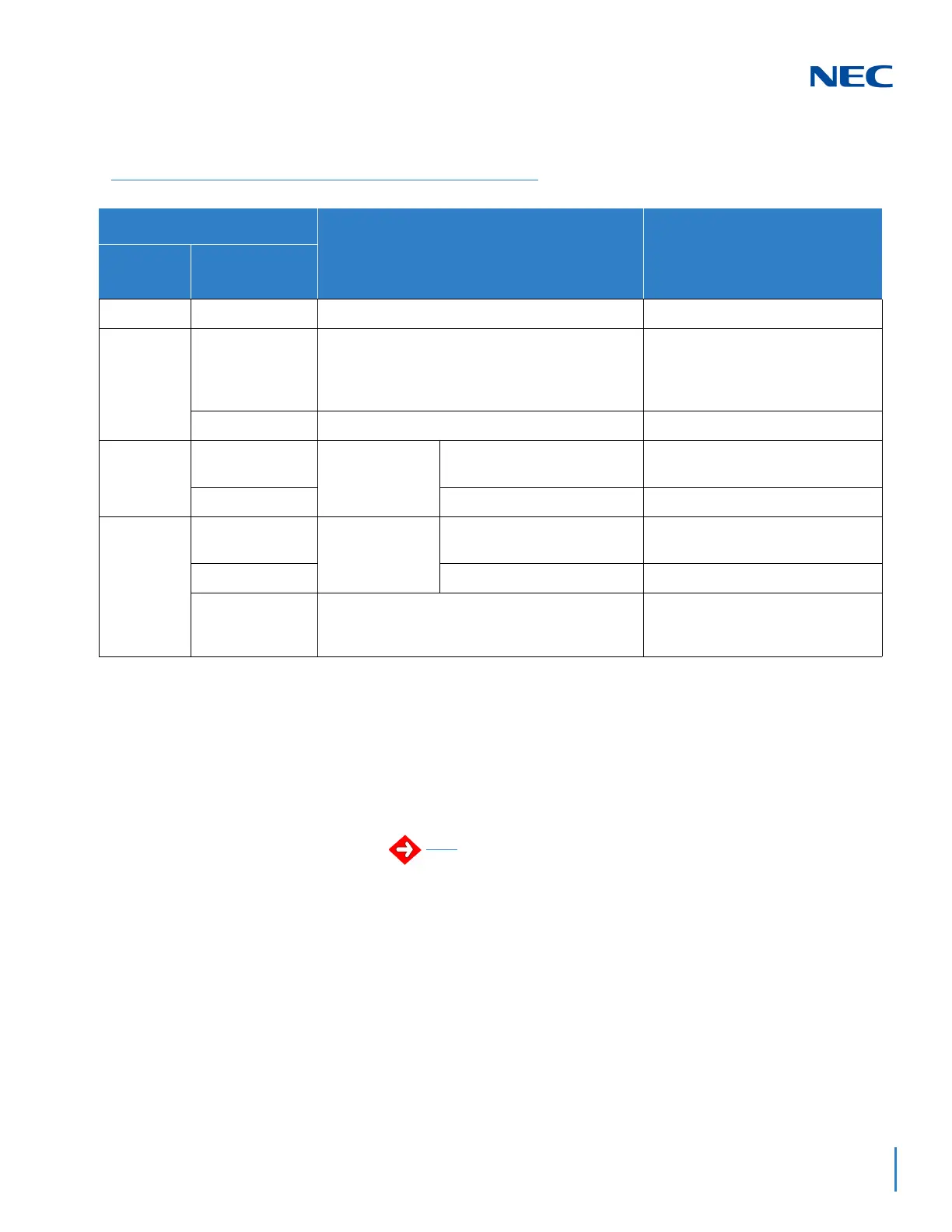
Table 4-13 GCD-8DLCA/GCD-16DLCA LED Indications
LED Indication
Operation Status Remarks
Live LED
(Green)
Busy LED
(Red)
On
On System Initializing
–
Flash (1s) On The assignment of the unit is refused.
When you exceed the system
capacity.
When the main software version
is not matched.
Flash (1s) Trouble found during self-diagnostics.
–
Flash
(100ms)
On
Normal
Operation
A Channel is busy (use
another from CH1 ~ CHx).
–
Off
All channels are idle. –
Off
On
Unit Busy
A Channel is busy (use
another from CH1 ~ CHx).
–
Off
All channels are idle. –
Flash 80ms
(On/Off) x 3/
400ms Off
Downloading firmware.
–
Any cabling to the DLCA blade must be in the building - no
outside cabling is permitted.

 Loading...


