Issue 3.0
3-30 Installing the SV9100 Chassis
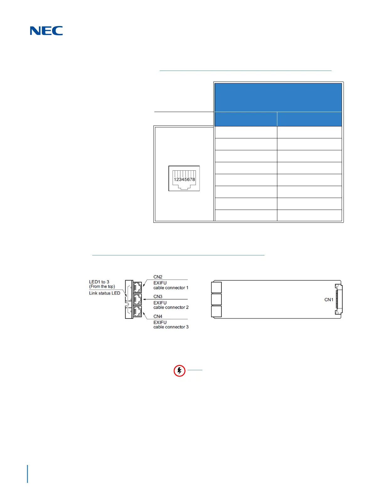
3.5.2.1 Connector Pin-Out on the GPZ-BS10/GPZ-BS11
3.5.2.2 Install the GPZ-BS10 Expansion Base Blade in the
CHS2UG B-US Controlling Chassis
1. Ensure the chassis is powered down.
2. Locate the door positioned on the left end (expansion bay)
of the Controlling Chassis.
3. From the right side of the door, pinch the Door Clip and pull
the cover outward to expose the expansion bay (refer to
Figure 3-37 CHS2UG B-US Expansion Bay on page 3-31).
Table 3-4 GPZ-BS10/GPZ-BS11 Connector Pin-Out
RJ-61 Cable Connector
GPZ-BS10 – CN2, CN3, CN 4
GPZ-BS11 – CN3
Pin No. Connection
1HW_UP (+)
2HW_UP (-)
3HW_DWN (+)
4FS (+)
5FS (-)
6HW_DWN (-)
7 CK8M (+)
8 CK8M (-)
Figure 3-36 GPZ-BS10 Components
Do not remove or install this blade with the power
on.

 Loading...


