Issue 3.0
4-98 Installing the SV9100 Blades
The T1 interface has a single 24 channel 64kb/s digital signal circuit which
can be configured either for T1 trunking.
Refer to the following tables for maximum upgrade capacities of the
GCD-CCTA blade:
Table 2-6 SV9100 Maximum 9.5” Gateway and 19” System
Capacities – Blades on page 2-12
Table 2-7 SV9100 Maximum 9.5” Base and Expansion System
Capacities – Blades on page 2-14
6.3.2 Installation
Install the GCD-CCTA in any universal slot.
6.3.3 LED Indications
LED indications for the GCD-CCTA are listed in Table 4-39 GCD-CCTA LED
Indications. Each LED is listed with its associated function and LED and
Operational status.
Refer to Figure 4-41 GCD-CCTA LED Indication Pattern of Layer 1 on T1
Unit on page 4-99 for LED pattern information.
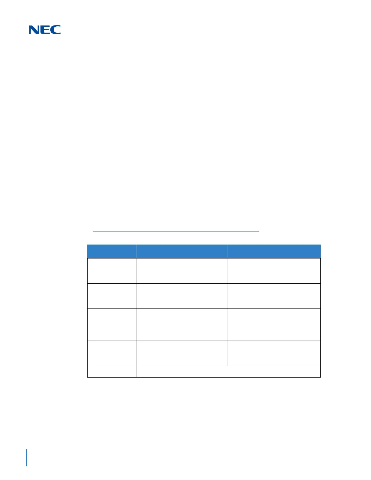
Table 4-39 GCD-CCTA LED Indications
Alarm Details of the Alarm LED Indication Pattern
LOS
Loss of Signal (Red Alarm)
No Signal (Analog Interface)
Following an alarm blink (red,
green, red, green) a Red LED
lights.
AIS
Alarm Indication Signal
(Blue Alarm)
Following an alarm blink (red,
green, red, green) a Red LED
slowly flashes On and Off twice.
OOF
Out Of Frame (Red Alarm) Following an alarm blink (red,
green, red, green) a Red LED and
Green LED flash On and Off three
times simultaneously.
RAI
Remote Alarm Indication (Yellow
Alarm)
Following an alarm blink (red,
green, red, green) a Green LED
flashes On and Off twice.
No Alarm
The system does the LED control.
The order of priority is set up to alarm in the order LOS
AIS
OOF
RAI.

 Loading...


