Issue 3.0
4-6 Installing the SV9100 Blades
2.2.2 Order of Installing Extension Blades
The order in which the station blades (GCD-8DLCA with GPZ-8DLCB,
GCD-16DLCA, GCD-4LCA, and GCD-8LCA with GPZ-8LCE) are physically
inserted determines the numbering plan.
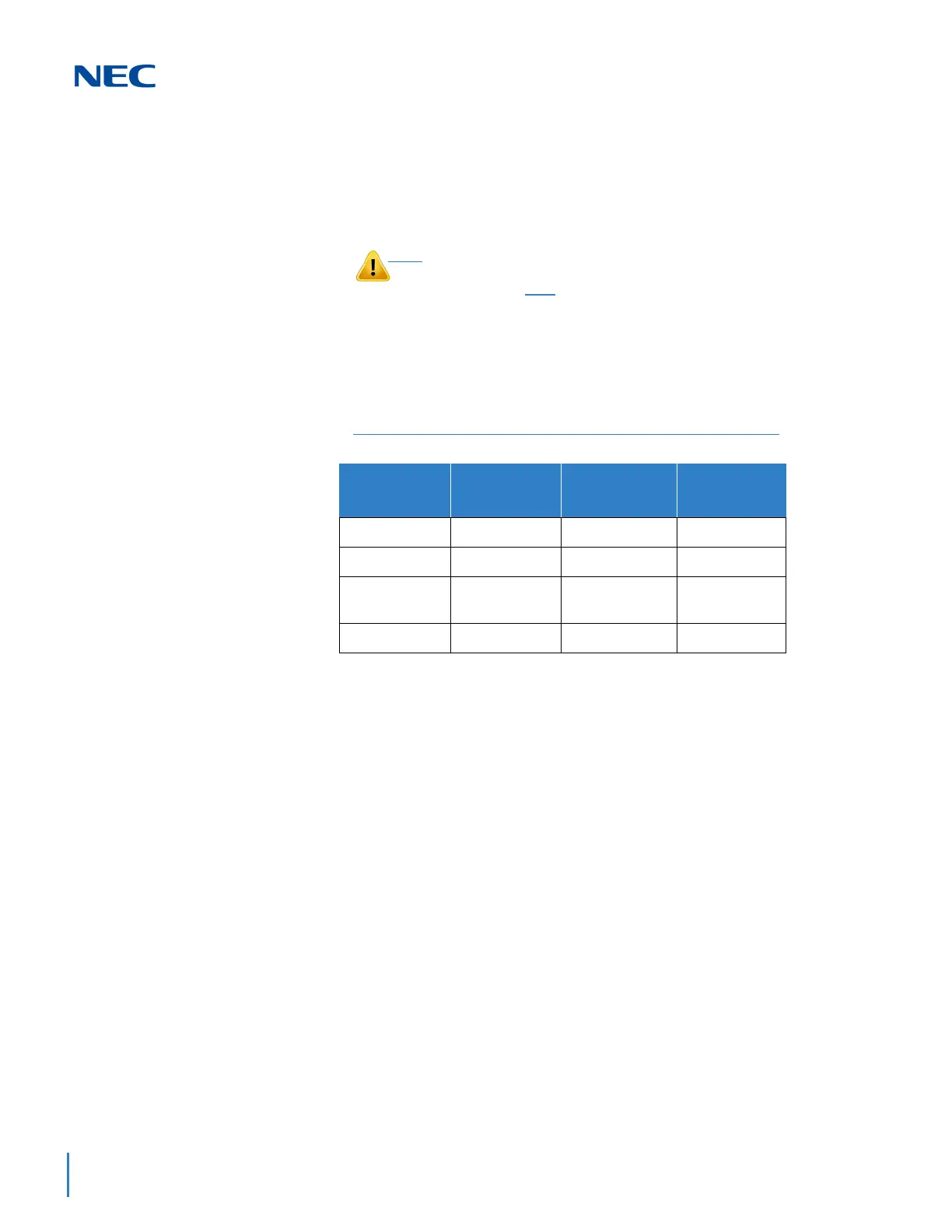
For example, when a digital station blade (GCD-16DLCA) is in Slot 1 (ext.
101~116) and three additional digital station blades are installed in the
following order, the numbering plan below in Table 4-1 Extension Blade
Installation Order Example applies.
After the initial powering up of the system, subsequent powering up or reset
does not change the slot identification. Program 90-05 must be performed
to change the slot identification.
Adding any daughter board to increase the available ports or go to a higher
capacity blade (e.g., GCD-16DLCA) may require that the slot be deleted in
programming and the blade reinstalled. In the following example, to add a
daughter board to slot 2, the blade must be removed, deleted in Program
90-05-01 or through WebPro Blade Configuration, then reinstalled with the
daughter board attached, otherwise the additional ports are not recognized.
This however, uses new ports for the combined blade – the initial ports
(ports 17~24 using the example below) are not used.
To avoid unexpected extension/trunk numbering if the VoIP or
Voice Mail daughter board registers with the system first, install
these boards after
the other extension and trunk blades are
installed.
Table 4-1 Extension Blade Installation Order Example
Order of
Installation
Blade Slot
Number
Blade
Extension
Numbers
11
GCD-16DLCA
101~116
22
GCD-16DLCA
117~132
34
GCD-8DLCA
GPZ-8DLCB
133~148
43
GCD-8DLCA
149~156

 Loading...


