Issue 3.0
4-24 Installing the SV9100 Blades
3.1.5 Connectors
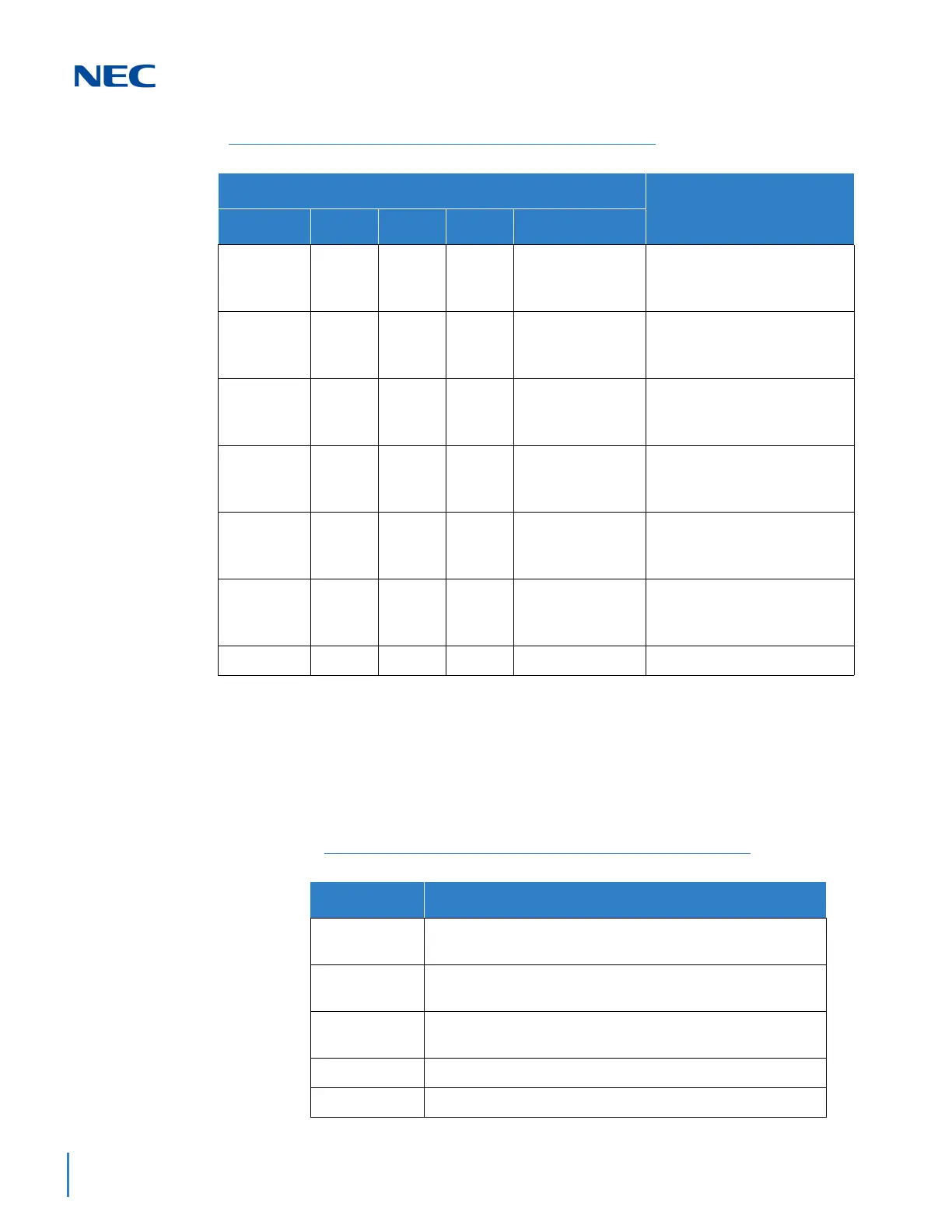
Table 4-9 GCD-CP10 Connections describes each connector on the
GCD-CP10
, Table 4-10 GCD-CP10 RJ45 Cable Connector Pin-Outs
describes the pin-outs for connectors on the GCD-CP10. Refer to Figure
4-6 GCD-CP10 Blade Layout on page 4-15 for the location of the
connections on the GCD-CP10 blade.
Blinking Off On Off On Steady When
USB Memory is
Installing
SRAM error
Blinking Off On On On Steady When
USB Memory is
Installing
SD memory booting error
Blinking On On On On Steady When
USB Memory is
Installing
SD memory data error
Blinking Blinking Blinking Blinking On Steady When
USB Memory is
Installing
Reading error of system
program
Blinking On Off Off On Steady When
USB Memory is
Installing
Error: Major alarm occurred
Blinking Blinking Off Off On Steady When
USB Memory is
Installing
Error: Minor alarm occurred
On Off Off Off Off
System starting up
Table 4-8 GCD-CP10 LED Indications (Continued)
LED Indication
Status
RUN (D23) D20 D21 D22 D25
Table 4-9 GCD-CP10 Connections
Connector Connector Description
J13
USB Memory Connection (used for upgrading software or
downloading system data)
J4
Ethernet Cable Connection (for PCPro or WebPro, CTI,
ACD MIS, IP Phone)
J11/J12
Pin Jack for External Source Connection (External MOH,
External Speaker, etc.)
J10
External Source Control Connection
J6/S4
Used for Debug

 Loading...


