Issue 3.0
SV9100 System Hardware Manual 4-99
6.3.4 Connectors
Table 4-40 GCD-CCTA RJ-45 Cable Connector Pin-Outs shows the
pin-outs for the RJ-45 connector. Figure 4-40 GCD-CCTA Blade on page
4-97 shows the location of the connectors on the GCD-CCTA blade.
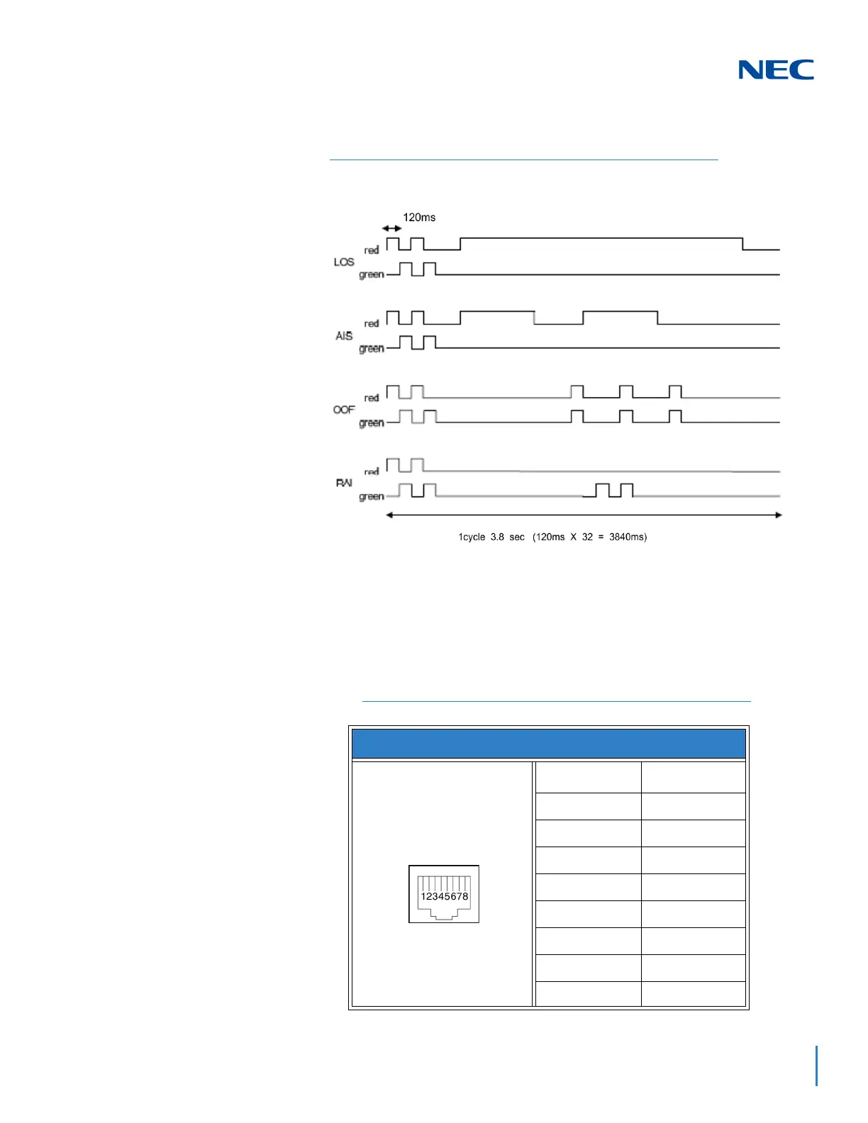
Figure 4-41 GCD-CCTA LED Indication Pattern of Layer 1 on T1 Unit
Table 4-40 GCD-CCTA RJ-45 Cable Connector Pin-Outs
RJ-45 Cable Connector – CN2
Pin No. Connection
1RA
2RB
3—
4TA
5TB
6—
7—
8—

 Loading...


