Issue 3.0
3-54 Installing the SV9100 Chassis
4.2.1.1 Wall Mounting the 9.5” Base (CHS2UG B-US) and
Expansion (CHS2UG E) Chassis
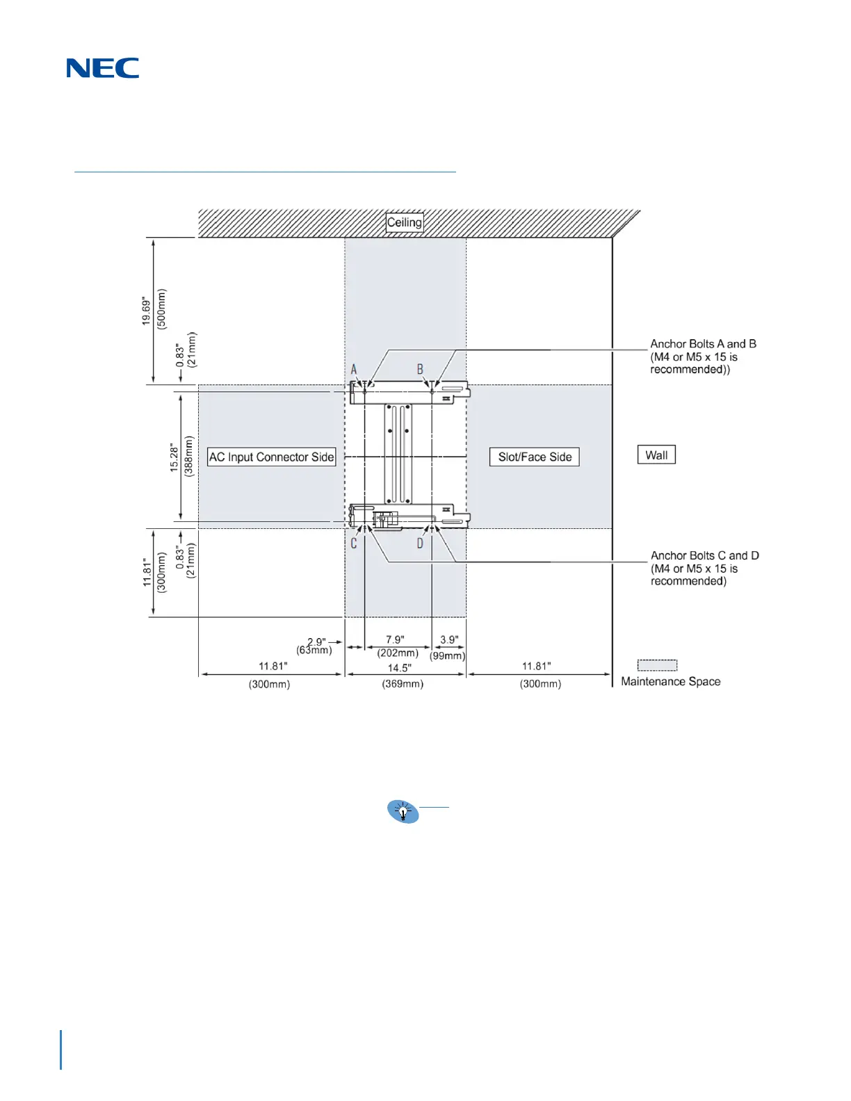
1. Use the template shown in Figure 3-65 Wall Mount Spacing
Guide (Base and Expansion Chassis) for required spacing
before drilling.
2. Mark and drill four holes marked A, B, C and D.
3. Mount Anchor bolts (locally procured), in holes A and B
drilled in step 2.
Because the bracket (upper) will be hooked onto the head
of the anchor bolts, allow the head to protrude
approximately 0.14 to 15 in (3.5 to 4.0mm) from the wall
(refer to (Figure 3-66 Anchor Bolt from Wall (9.5”
Chassis) on page 3-55).
Figure 3-65 Wall Mount Spacing Guide (Base and Expansion Chassis)
Plywood should first be installed on the wall where
the chassis will be positioned. This allows secure
anchoring of the screws, which support the weight
of the chassis.

 Loading...


