Issue 3.0
3-36 Installing the SV9100 Chassis
EXAMPLE:
0 CHS2UG-US (19” Chassis) & 4 CHS2UG B-US/CHS2UG E
(9.5” Base Chassis/9.5” Expansion Chassis)
1 CHS2UG-US (19” Chassis) & 3 CHS2UG B-US/CHS2UG E
(9.5” Base Chassis/9.5” Expansion Chassis)
2 CHS2UG-US (19” Chassis) & 2 CHS2UG B-US/CHS2UG E
(9.5” Base Chassis/9.5” Expansion Chassis)
3 CHS2UG-US (19” Chassis) & 1 CHS2UG B-US/CHS2UG E
(9.5” Base Chassis/9.5” Expansion Chassis)
4 CHS2UG-US (19” Chassis) & 0 CHS2UG B-US/CHS2UG E
(9.5” Base Chassis/9.5” Expansion Chassis)
3. Repeat for additional Expansion Chassis.
3.5.3 Installing Grounding on 9.5” Base and Expansion Chassis
1. Ensure the 9.5” chassis is powered off and the AC power cord is
unplugged.
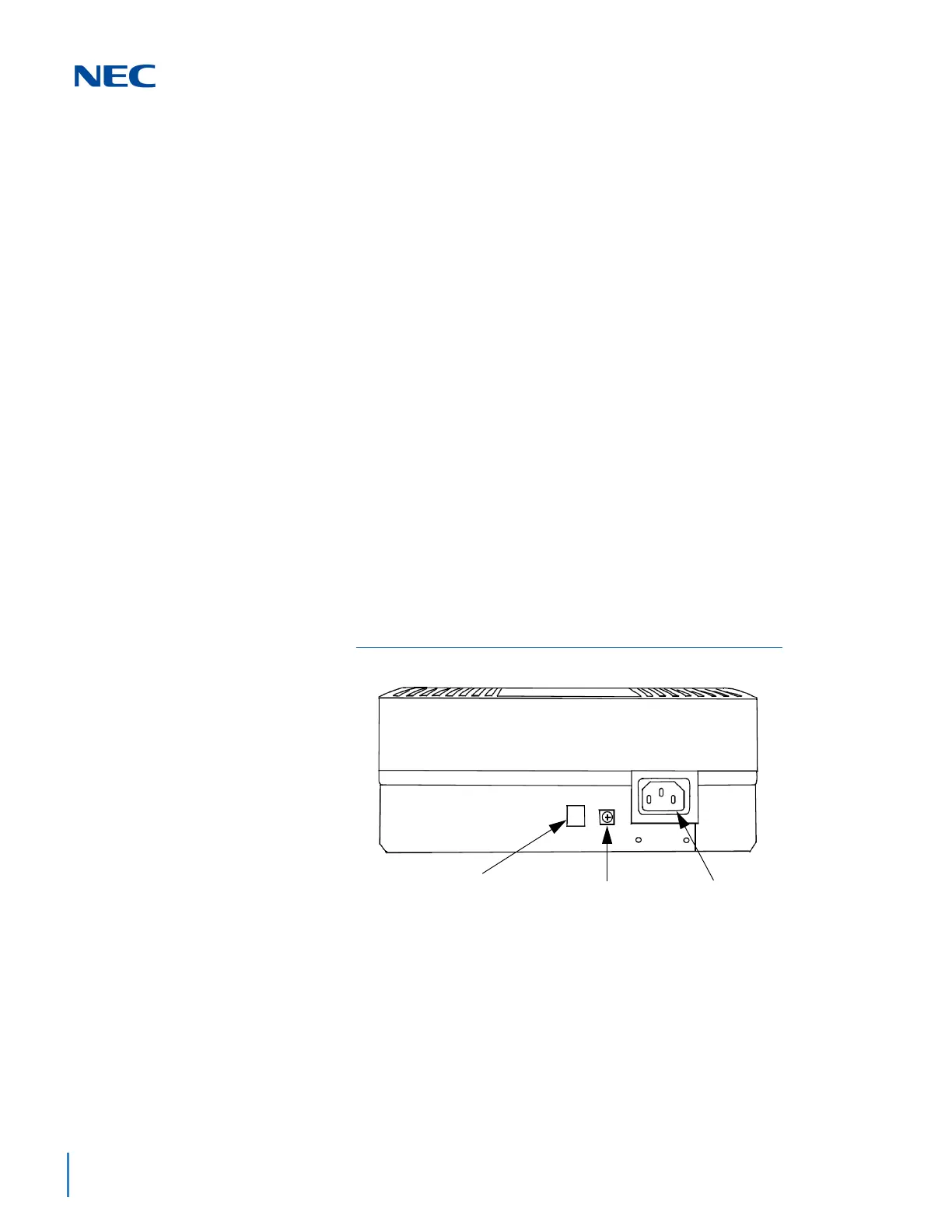
2. Ground the chassis [refer to Figure 3-45 9.5” Chassis (Rear View)] by
connecting a 14 AWG wire from the FG lug on the back side of the
chassis to an electrical service ground (such as a cold water pipe).
The CHS2UG E (9.5” expansion chassis) does not have an FG
lug.
Figure 3-45 9.5” Chassis (Rear View)
Ground
AC Inlet
For External Battery
(12V Connection)
CHS2UG

 Loading...


