Issue 3.0
SV9100 System Hardware Manual 3-35
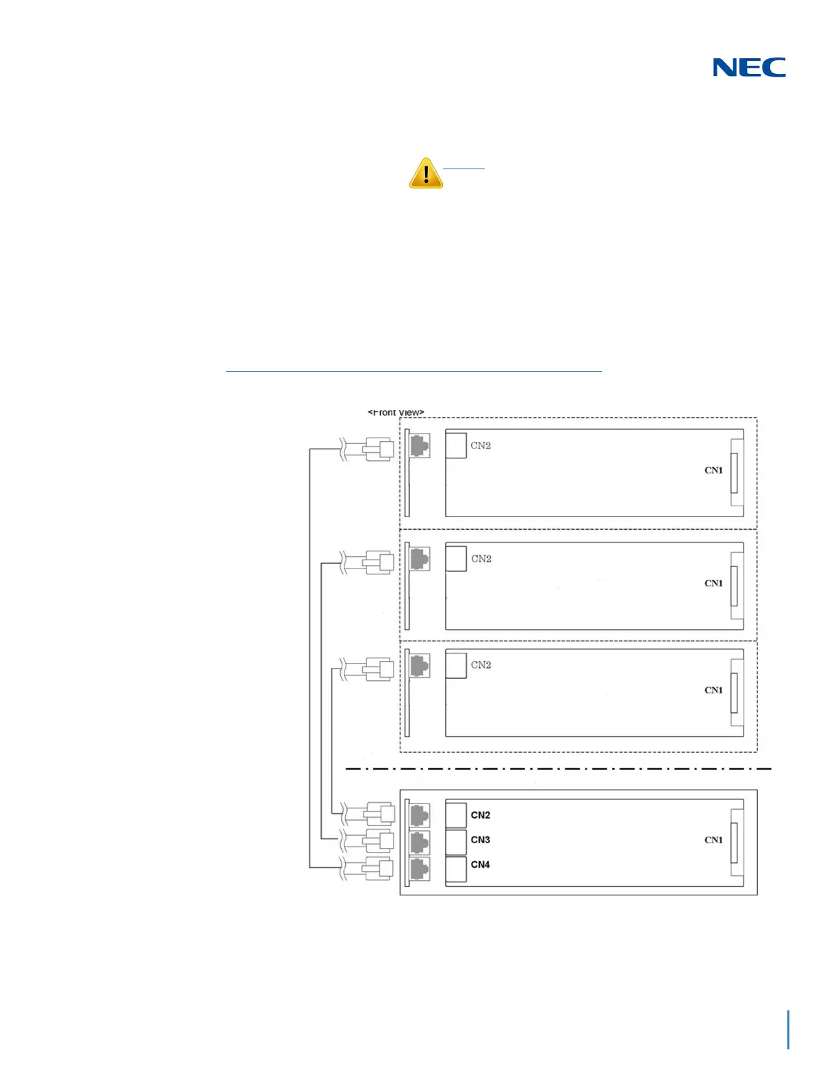
3.5.2.4 Connect the Controlling and Expansion Chassis
1. Ensure Controlling and Expansion chassis are powered
down.
2. Using the NEC provided CAT5 straight-through cable(s),
attach one end to each Expansion Chassis CN2 connector
on the GPZ-BS11 blade (see Figure 3-44 System Expansion
Cabling). Attach the opposite end to the CN2, CN3 or CN4
connector on the GPZ-BS10 of the Controlling Chassis.
Installment of the GPZ-BS10 blade and
GPZ-BS11 blade(s) must be completed prior to
installation of the provided (CAT 5) expansion
cabling
Figure 3-44 System Expansion Cabling
Install in Controlling
Chassis
Install in Expansion
Chassis
Install in Expansion
Chassis
Install in Expansion
Chassis

 Loading...


