Issue 3.0
SV9100 System Hardware Manual 3-27
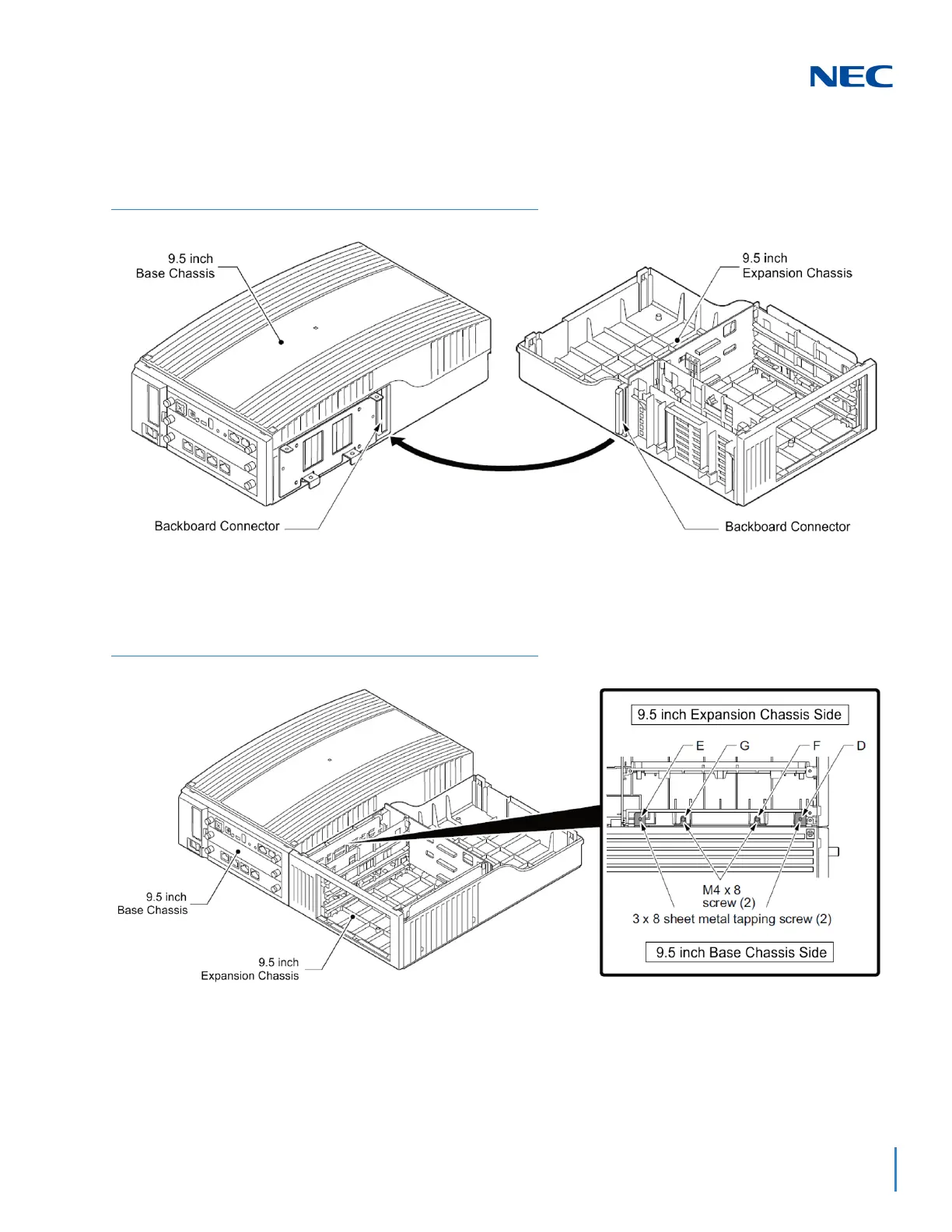
5. Align the Backboard Connector on the Expansion and Base chassis
(refer to Figure 3-32 Connecting the Base and Expansion Chassis),
and push the two chassis together.
6. Secure the Base and Expansion chassis using four screws in holes D
and E on the top (refer to Figure 3-33 Securing the Expansion
Chassis to the Expansion Bracket), and holes F and G on the bottom.
7. Slide the Expansion Chassis cover into place. Using two screws in
holes d and e (refer to Figure 3-34 Install Expansion Chassis Cover
on page 3-28) secure the Expansion Chassis cover.
Figure 3-32 Connecting the Base and Expansion Chassis
Figure 3-33 Securing the Expansion Chassis to the Expansion Bracket

 Loading...


