Issue 3.0
SV9100 System Hardware Manual 9-5
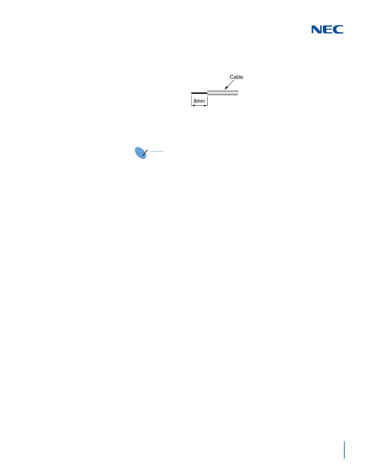
4. Strip one end of the cable to be connected to the control relay or door box
so that approximately 1/4” (8mm) of bare wire is exposed.
5. Insert the cable into the proper CN4 or CN5 location while holding down the
lock button (holding down this lock button is easiest with a flat-head
screwdriver). Once the cable is in place, release the lock button.
Refer to the specific function being connected for more detail on
PGD(2)-U10 ADP connections.

 Loading...


