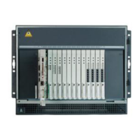
Configuration diagrams
Issue 2.1 June 2006 1073
6. PN (G650 Media Gateway stack, MCC1 Media Gateway, SCC1 Media Gateway stack), that consists of at least two media
gateways or carriers. The figure shows a G650 stack and an SCC1 stack
7. PN control gateway or carrier that contains two TN570 EI circuit packs for bearer and control network connections to the
other two PNs.
NOTE: One TN2182 tone clock circuit pack must also be present per PN if the PN consists of SCC1 or MCC1 Media
Gateways. One maintenance-only TN2312BP IPSI circuit pack must be present per PN if the PNs consists of G650
Media Gateways.
The control gateway or carrier is always in the A position in the MCC1 or gateway stack.
8. IPSI-to-server control network connection through the Ethernet switch.
9. TN 570/570 fiber connections between PNs.
10. Customer LAN
11. LAN connections of an optional TN2302AP IP Media Interface or a TN2602AP IP Media Resource 320 for IP-TDM voice
processing, if any, and an optional TN799DP CLAN for control of IP endpoints
NOTE: The number of TN2302AP, TN2602AP, and TN799DP circuit packs varies, depending on the number of IP
endpoints, PNs, and adjunct systems. These circuit packs are optional for PNs in a direct-connect network and can
be inserted into a port carrier as shown in the figure, the PN control carrier or the duplicated control carrier. However,
the CLAN circuit pack is required for downloads of firmware updates.
12. LAN connections of media servers for remote administration.
13. Duplicated server links, including the link for translations transfer and the link for control data sharing.
Figure notes: S8700-series direct-connect configuration with duplicated control network
2 of 2

 Loading...