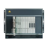
Migrating translations
Issue 2.1 June 2006 777
The information in this section is based on the assumption that the S8700 Series Media Servers
have the latest software release, and that the media server complex is installed, configured, and
operational.
This section covers the following tasks:
● Connecting the media server cables and the IPSI cables to the Ethernet switch on
page 777
● Upgrading the hardware in each port network on page 777
● Installing Expansion Interface circuit packs on page 785
● Post-migration administration on page 789
Connecting the media server cables and the IPSI cables to the
Ethernet switch
Note:
Note: For a connectivity guide, see Quick Start for Hardware Installation: Avaya S8700
Series Media Server (555-245-703).
Each TN2312BP IP Server Interface (IPSI) circuit pack must have a CAT5 Ethernet cable that
connects back to the Ethernet switch. Cables for IPSIs that are located in PN carrier A are
GREEN. Cables for IPSIs that are located in PN carrier B (high or critical reliability) are RED.
In duplex configurations, each media server is connected to the Ethernet switch or switches that
comprise control network A (CNA) (GREEN cable).
In high-reliability and critical-reliability configurations, each media server is connected to the
Ethernet switch or switches that comprise control network B (CNB) (RED cable).
Upgrading the hardware in each port network
In IPSI-controlled PNs, you must replace the existing tone clock and the maintenance circuit
packs with a TN2312BP IPSI circuit pack and TN775D or later maintenance circuit pack,
respectively. You also must replace the TN570 (R) Expansion Interface circuit packs with
TN570B, vintage 7 or later, circuit packs.
This section contains the following information:
● Replacing tone-clocks with IPSI circuit packs and replacing maintenance circuit packs on
page 778
● Using DHCP addressing on page 791
● Completing circuit pack replacement on page 785

 Loading...