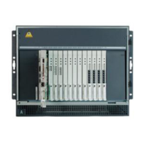
Migrating a DEFINITY Server R to an S8700-Series Media Server
782 Upgrading, Migrating, and Converting Media Servers and Gateways
High-reliability or critical-reliability configuration
To set up a high-reliability or critical-reliability configuration:
Note:
Note: You can replace the maintenance circuit pack with the TN775D Maintenance
(EPN) (if necessary) and the TN2182 Tone Clock circuit packs with the
TN2312BP Internet Protocol Server Interface (IPSI) circuit packs. You can
program these circuit packs ahead of time. All the circuit packs being replaced
are hot-swappable, so you do not need to turn off the PNs or the carrier.
These procedures assume that the tone clock and maintenance circuit packs are in the A and B
carriers. If one of them is in the E or D rather than B carrier, the ribbon cable is not necessary.
1. Determine which PNs get the IPSI circuit packs. See Determining IPSI placement in port
networks on page 778.
Note:
Note: Not all PNs require an IPSI circuit pack.
2. Type list configuration control. Press Enter to determine which port networks
contain TN2182 Tone Clock circuit packs and which media gateway contain the circuit
packs.
3. Type status port-network number where number is the number of the port network.
Press Enter to determine the active tone clock.
4. If needed, type set tone-clock cabinet carrier where cabinet is 1-64 and
carrier is A-E. Press Enter to make the Tone Clock in the B carrier active.
5. Remove the TN2182 Tone Clock circuit pack from the standby carrier (A). Place the circuit
pack in an antistatic carrier.
Note:
Note: If present, do not remove the TN771 Maintenance/Test circuit pack.
6. Remove the TN775B/C Maintenance/Test circuit pack from standby carrier (A). Place the
circuit pack in an antistatic carrier.
7. Insert the TN2312BP Internet Protocol Server Interface (IPSI) circuit pack part way into the
TONE-CLOCK slot on the standby carrier (A).
8. Attach one end of the short ribbon cable to the connector on the component side of the
circuit pack. The red line must be on the bottom (pin 1).
9. Push the tabs on the ends of the connector inward to lock the connector in place. See
Ribbon cable connector
on page 780.
10. Thread the ribbon through the slot on the front panel.
11. Insert the TN775D Maintenance (EPN) circuit pack part way into the MAINTENANCE slot in
carrier A.

 Loading...