Issue 2.1 June 2006 1229
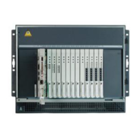
Figure 108: Replace the riser assembly
2. Slide the riser assembly in the slots until it rests on the base of the chassis and is aligned
with the two thumbscrew holes.
3. Tighten the two thumbscrews to secure the riser assembly in place.
Tip:
Tip: To start the thumbscrew use one hand to push the spring-loaded screw down into
the threaded hole, then turn the screw with the other hand.
Figure notes:
1.
Align tabs and insert
carrier into connector.
2.
Tighten both thumb screws.
2
3
VDCI
1
2
3
1
3
3
M
G
z
1
0
0
M
G
z
1
0
0
M
G
z
h3df87ci LAO 102505
DAL1
DUP
MEMORY
RECEIVE
MODE
LINC
SYNC
TRANS
MODE
LINC
ACTIVE
2
1
2

 Loading...