User Manual UMN:CLI
V5808
275
8.1.10.2 Shared VLAN
This chapter is only for Layer 2 switch operation. The V5808 is Layer 3 switch, but it can
be used for Layer 2 also. Because there is no routing information in Layer 2 switch, each
VLAN cannot communicate. Especially, the uplink port should receive packets from all
VLANs. Therefore, when you configure the V5808 as Layer 2 switch, the uplink ports
must be included in all VLANs.
default br2 br3
br4 br5
Outer Network
Uplink Port
SWITCH(bridge)# show vlan
u: untagged port, t: tagged port
-----------------------------------------------------------------
| 1 2 3 4
Name( VID| FID) |123456789012345678901234567890123456789012
-----------------------------------------------------------------
default( 1| 1) |u...uuuuuuuuuuuuuuuuuuuuuuuuuuuuuuuuuuuuuu
br2( 2| 2) |.u.....................u..................
br3( 3| 3) |..u....................u..................
br4( 4| 4) |...u...................u..................
br5( 5| 5) |....u..................u..................
SWITCH(bridge)#
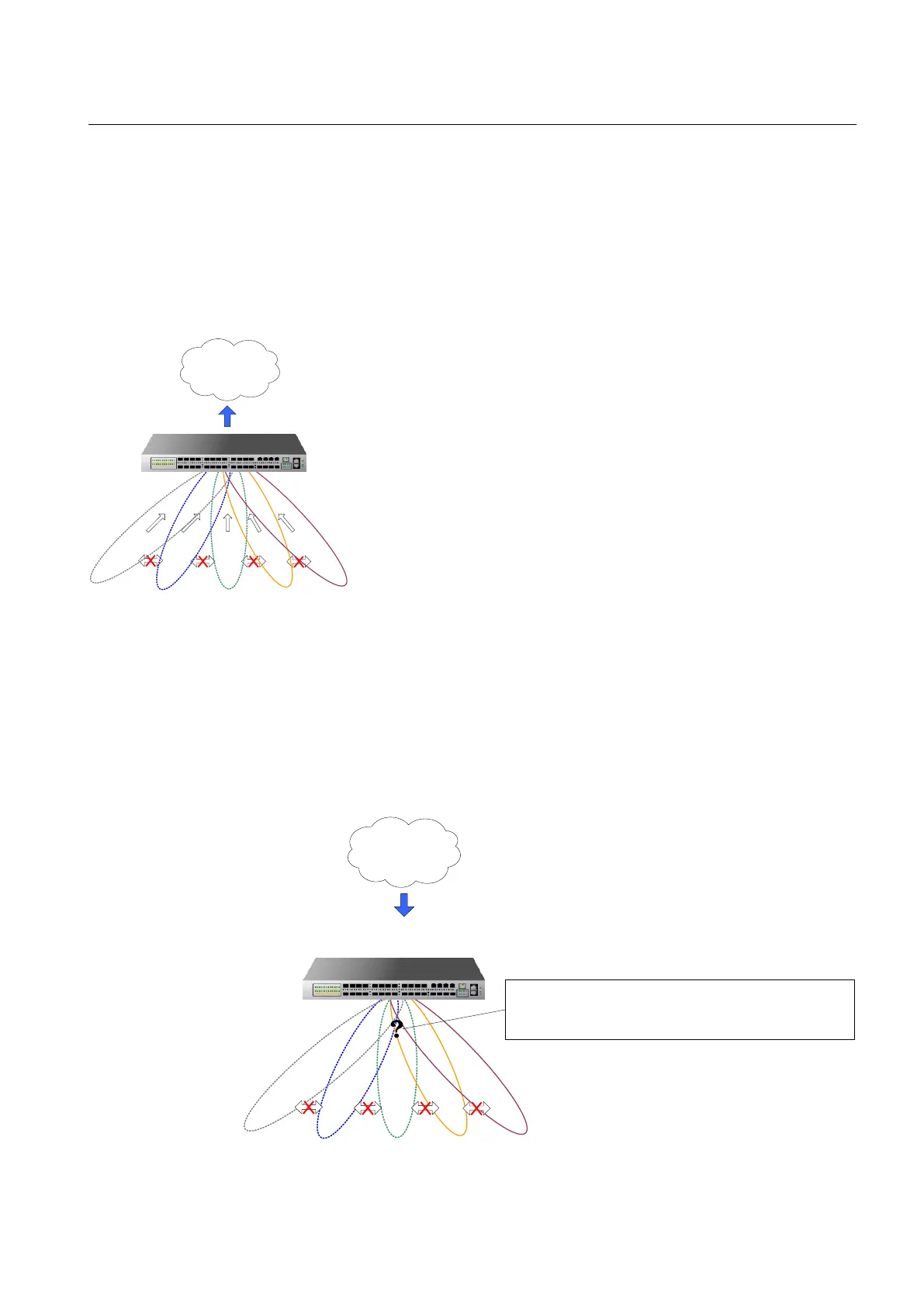
Fig. 8.5 Outgoing Packets under Layer 2 Shared VLAN Environment
As above configuration with untagged packet, if an untagged packet comes into port 1, it
is added with tag 1 for PVID 1. In addition, the uplink port 24 is also included in the
default VLAN; it can transmit to port 24.
However, a problem can occur for coming down untagged packets to uplink ports. If an
untagged packet comes to uplink ports from outer network, the system does not know
which PVID it has and where should it forward.
default br2 br3
br4 br5
Outer Network
Uplink Port
Untagged packets comes from the uplink ports. The
packets should be forwarded to br3, but the system
cannot know which PVID added to the packet.
Fig. 8.6 Incoming Packets under Layer 2 Shared VLAN Environment (1)


 To Next Page