User Manual UMN:CLI
V5808
29
Illustrations
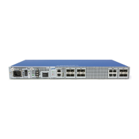
Fig. 2.1 Front View of the V5808 ................................................................................. 36
Fig. 3.1 Overview of Configuration Mode .................................................................... 49
Fig. 4.1 Structure of IPv6 Header ................................................................................ 80
Fig. 4.2 Process of 802.1x Authentication ................................................................... 91
Fig. 4.3 Multiple Authentication Servers ...................................................................... 92
Fig. 5.1 Port Mirroring ................................................................................................ 106
Fig. 6.1 Ping Test for Network Status ........................................................................ 128
Fig. 6.2 IP Source Routing ........................................................................................ 129
Fig. 7.1 Procedure of QoS operation ........................................................................ 175
Fig. 7.2 Structure of Rule........................................................................................... 176
Fig. 7.3 Token Bucket Meter ..................................................................................... 185
Fig. 7.4 Behavior of srTCM (1) .................................................................................. 186
Fig. 7.5 Behavior of srTCM (2) .................................................................................. 187
Fig. 7.6 Bahavior of srTCM (3) .................................................................................. 187
Fig. 7.7 Behavior of trTCM (1) ................................................................................... 188
Fig. 7.8 Behavior of trTCM (2) ................................................................................... 189
Fig. 7.9 Behavior of trTCM (3) ................................................................................... 189
Fig. 7.10 Strict Priority Queuing .................................................................................. 200
Fig. 7.11 Deficit Round Robin ..................................................................................... 201
Fig. 7.12 Weighted Round Robin ................................................................................ 201
Fig. 7.13 WRED Packet Drop Probability .................................................................... 205
Fig. 7.14 NetBIOS Filtering ......................................................................................... 211
Fig. 7.15 Proxy ARP .................................................................................................... 230
Fig. 7.16 ICMP Message Structure ............................................................................. 244
Fig. 8.1 Port-based VLAN ......................................................................................... 261
Fig. 8.2 Subnet-based VLAN .................................................................................... 264
Fig. 8.3 Example of QinQ Configuration ................................................................... 267
Fig. 8.4 QinQ Frame .................................................................................................. 268
Fig. 8.5 Outgoing Packets under Layer 2 Shared VLAN Environment ..................... 275
Fig. 8.6 Incoming Packets under Layer 2 Shared VLAN Environment (1) ................ 275
Fig. 8.7 Incoming Packets under Layer 2 Shared VLAN Environment (2) ................ 276
Fig. 8.8 Link Aggregation........................................................................................... 280
Fig. 8.9 Example of Loop .......................................................................................... 287
Fig. 8.10 Principle of Spanning Tree Protocol ............................................................. 287
Fig. 8.11 Root Switch .................................................................................................. 288
Fig. 8.12 Designated Switch........................................................................................ 289
Fig. 8.13 Port Priority ................................................................................................... 290
Fig. 8.14 Port States .................................................................................................... 290
Fig. 8.15 Alternate Port and Backup port .................................................................... 292
Fig. 8.16 Example of Receiving Low BPDU ................................................................ 293
Fig. 8.17 Convergence of 802.1d Network .................................................................. 294
Fig. 8.18 Network Convergence of 802.1w (1)............................................................ 294
Fig. 8.19 Network Convergence of 802.1w (2)............................................................ 295
Fig. 8.20 Network Convergece of 802.1w (3).............................................................. 295
Fig. 8.21 Compatibility with 802.1d (1) ........................................................................ 296
Fig. 8.22 Compatibility with 802.1d (2) ........................................................................ 296
Fig. 8.23 CST and IST of MSTP (1) ............................................................................ 297
Fig. 8.24 CST and IST of MSTP (2) ............................................................................ 298
Fig. 8.25 Example of PVSTP....................................................................................... 308